DreamMaker FX Documentation
Introduction
Welcome the DreamMaker FX! This is an audio platform that designed to help musicians and effect designers to explore and create effects and synths that have never been heard before.
It is designed to be accesible for experienced programmers and those who have done no programming.
At its core, this platform consists of a microprocessor connected to a powerful SHARC DSP. SHARC DSPs are specialized audio processors used in lots of high-end audio gear. But we don’t need to worry about writing DSP code or dealing with the complexities of DSP system design.
Beyond audio processing, the DreamMaker FX hardware offers lots of options for expanding the hardware. External sensors can be easily wired and connected to various effect parameters.
Option 1: No programming at all!
When you plug the DreamMakerFX pedal into your Mac or PC, it will show up as a mounted drive (DM_FX). You can download a “UF2” file of the sketch right to that drive and it will start running. This is a great option if you have no interest in programming and just wnat to start playing through some of the creations you find on this site!
Option 2: Start building your own creations with Arduino
Arduino is a programming platform that is designed to make programming easier and more accessible than it normally is. With just a few lines of code, you can begin creating your own pedal creations.
There are a few ways you can get started:
Download a “pedal pack” from the Browse Pedals page and start playing with these
Download a pedal design that someone else has created on this site.
Start with the Basic echo pedal tutorial and start building from the ground up!
What is that word, Arduino?
Have you heard about Arduino? If not, Arduino is this little circuit board created about 10 years ago which was designed to make programming hardware easy. I won’t bore you with the details but that shit got huge. Now lots of people make Arduino-compatible boards (that use their simple programming software) and accessory boards with sensors and other batshit crazy stuff.
So rather than learning some arcane programming language and software tools, you’re using one of the easiest programming tools ever created. And there are plenty of resources for learning and getting help out there. Here’s a great set of tutorials to get started if you’re new to Arduino in general:
https://www.arduino.cc/en/Tutorial/HomePage?from=Main.Tutorials
Okay, so buckle in and get ready to blow some minds.
Hear it in action
Here are a few examples of effects created on the DreamMaker FX Platform.
Perpetuity
Link to effect on DreamMakerFx.com: https://www.dreammakerfx.com/pedal-designs/Perpetuity
This effect allows you to “catch” a note which will ring out indefinitely.
Hold down the left footswtich to “catch” a note which will ring out indefinitely. Press and hold down the left footswitch to layer on more notes to create a sonic canvas to play over. Tap the right footswitch to release the held notes. When the left footswich is held down to capture notes, the clean channel is muted so you only hear the swell of the capture droning notes. This effect works by running the notes through an ADSR envelope so it quickly fades in and then fades out. This audio is then sent to four delay lines that are staggered so the attack / decay of the note becomes a solid wall of sound.
Pentatonic Theramin
Link to effect on DreamMakerFx.com: https://www.dreammakerfx.com/pedal-designs/Pentatonic-Theramin
This effect doesn’t use an instrument at all. Or rather, you are the instrument. This effect requires a SparkFun distance sensor connected to the sensor port on the DreamMaker FX (https://www.sparkfun.com/products/14722).
It uses the synth engine along with some gentle effects to create a theramin that operates over the pentatonic scale. And when there is nothing in front of the sensor, the tones turn off.
Sensors can be wired to really any effect parameter so it creates a lot of interesting opportunities for new kinds of expression.
Multitudes
Link to effect on DreamMakerFx.com: https://www.dreammakerfx.com/pedal-designs/Multitudes
A cool, multi-layer delay effect created by Joe Dougherty. Consists of a variable length delay pedal where the feedback path of the main delay (“driver”) is routed to a secondary delay (“propagator”).
Stereo Reverb
With the immense amount of processing power and on-board RAM, we can create very rich, intricate reverbs using a few of the building blocks (multi-tap delays, all-pass filters, biquad filters, variable delays, and regular delays).
Here’s an example of a stereo reverb that consumes about 10% of the available processing resources on the SHARC DSP.
Polyphonic Guitar Synth
Link to effect on DreamMakerFx.com: https://www.dreammakerfx.com/pedal-designs/Polyphonic-guitar-synth-pedal
The DreamMaker FX platform can track multiple notes being played simultaneouly and create various synth effects from these notes.
This is a polyphonic guitar synth meaning that it tracks multiple strings. It uses an FM synth engine along with ADSR envelope generator and an output filter. The pedal is configured by default to use a triangle (OSC_TRIANGLE) wave that is modulated with a sine wave (OSC_SINE). However, lots of interesting sounds can be created by swapping these out with out types of oscillators (e.g. OSC_SQUARE, OSC_RAMP_POS, OSC_RAMP_NEG, OSC_RANDOM, etc).
Meet the Hardware
Gen 1: The Dream Lemur
The first generation hardware was designed in the spring of 2019 and manufactured during the summer.
- Features:
450MHz SHARC DSP + SAMD51 processor (running Arduino stuff)
Stereo in / Stereo out @ 48kHz sampling rate
Short (QWIIC) and long range (CAT-5) sensor interfaces
Wireless sensor interface (via RF transceiver)
USB connector (for programming and debug)
3 pots
2 footswitches
2 red LEDs

Gen 2: The Beyonder
The design for the second generation hardware began as soon as we started using the first generation and realized all the things that could be improved. Our first gen-2 hardware is in house and working great so far.
- Features
450MHz SHARC DSP + SAMD51 processor (running Arduino stuff)
Stereo in / Stereo out @ 48kHz sampling rate
Expression pedal
MIDI in / out
Short (QWIIC) and long range (CAT-5) sensor interfaces
USB connector (for programming and debug)
5 pots
2 footswitches
3 RGB LEDs
2 3-way toggles

Installation
This page offers instructions for first time installs and subsequent updates. Half the fun of this platform is that it is always evolving with new modules and capabilities. Once you have the Arduino tools installed, you can check for DreamakerFX updates which bring with them new capabilities and enhancements!
First time installation
The DreamMaker FX hardware currently supports Windows 10, OS X, and probably Linux. If you’re running Windows 7, there are a few additional steps that are required to get the UF2 USB device drivers installed.
First order of business, let’s go download some free software and get rolling.
Download and install the Arduino IDE: https://www.arduino.cc/en/main/software
Accept the defaults
You may be prompted to install several additional drivers; install them.
If you’re running OS X Catalina, make sure you’re using Arduino v1.8.10 or later.
Click
Finishwhen the installs are complete.
Plug the Dream Lemur into an outlet, and connect to a USB port on your computer with a MicroUSB cable. Make sure the USB cable you are using is not a charging cable. There are lots of microUSB charging cables out there that just have wires for power and ground and no data! If you don’t see the
DM_FXdrive/volume show up on your computer, you may need to put your pedal into bootloader mode. See the Troubleshooting section for details on how to do this.Install the DreamMaker FX Arduino board package In the Arduino IDE:
Navigate to either
File->Preferenceson Windows, orArduino->Preferenceson Mac. If you’re using Linux, we assume you’re enough of a bad ass to figure out what to do.In the preferences window, find the text field toward the bottom called
Additional Boards Manager URLs.Copy and paste the following into that text field:
https://runjumplabs.github.io/arduino-board-index/package_dreammaker_fx_index.jsonClick OK to close the preferences window.
Navigate to
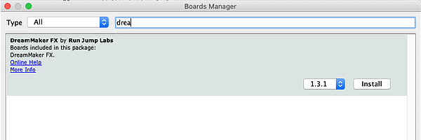
Tools->Board->Board Manager.Either type
dreamin the search box, or scroll down until you findDreamMaker FX by Run Jump Labs.Click
Install. This will take a few minutes; then hitClose.
 DreamMaker FX package
Select the DreamMaker FX hardeare
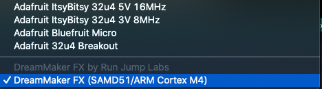
Navigate to
Tools->Board. At the very bottom of the list you should seeDreamMaker FX (SAMD51/ARM Cortex M4. Select it.
 DreamMaker FX package
Make some bitchin’ effects and play some rock and/or roll very loudly.
The setup process is very similar to Adafruit boards which use the same Arduino processor (Atmel SAMD51 family). This page may offer some additional help https://learn.adafruit.com/adafruit-metro-m4-express-featuring-atsamd51/setup.
Updating the DreamMaker FX Arduino package
There are always updates happening with new effects, bug fixes and improvements! When you do a first time install, you’ll have the latest and greatest. However, it’s always good to check back to see if there are updates.
In the Arduino program:
Navigate to
Tools->Board->Board Manager.Either type
dreamin the search box, or scroll down until you findDreamMaker FX by Run Jump Labs.Select the latest version from the pull-down menu; then hit
Update
A cool feature is that the firmware running on the DSP is automatically updated the first time you download a sketch after an update to the latest version. When you download the effect, you’ll see some messages in the serial monitor that the update is happening (just takes a few seconds). The firmware update only happens when the system detects that the firmware on the DSP is a different version than what is running in the Arduino code.
The Anatomy of an Effect
Let’s start by learning the anatomy of a basic Arduino “Sketch” (aka “program” in Arduino speak).
With the Arduino app open, go to File->New. You’ll see a new text editor window appear with a new “sketch”. This sketch will come pre-populated with two functions. One is called setup() and another is called loop().
When the sketch is downloaded to our hardware, it will first run any commands in the setup() function once. And then it will run the loop() function repeatidly. Each time you power up the board, it goes through the same sequence (run setup() once and then run loop() indefinitely).
When creating effects, there are three places we’ll add code.
First (in area #1), we’ll define / “declare” which effects building blocks we’ll be using at the very top of the file. We can declare up to 100 effect blocks (for example, if you wanted to create 100 delay lines and wire them together, go for it!).
Next (in area #2), we’ll define how these building blocks connect to the audio in / out jacks and to each other. We can also route control signals between the effect blocks here too.
Finally (in area #3), we’ll add any real-time controls of the effect parameters. This is where we, for example, respond to a pressed footswtich, changed knob or switch.
 Anatomy of an effect
While some effects may look complex at first glace, they all really have these three components.
Tutorial #1: Basic Delay Pedal
As mentioned earlier, one doesn’t have to be an experienced programmer to use this platform. The coding patterns for creating various effect and synth components, wiring them together and controlling their parameters is pretty straight forward.
Basic Arduino anatomy
Let’s start by creating a simple echo effect to see how the pieces fit together.
1. Add the effects library of functions
At the top of the file, we’ll add a line that will link in all of the functions, variables and objects that you’ll use to create your effects. At the very top of the file, add #include <dreammakerfx.h>. You’ll add this line to the top of every Arduino sketch you create for this platform.
// Include DreamMaker FX library of effects routines
#include <dreammakerfx.h>
2. Add any effects or synthesis objects
Above the setup routine, we will add (aka declare) any effect and synth objects that we’ll be using. When we add an object, in many cases we will also provide the initial parameters.
In this case, we are going to create a single echo / delay effect object and name it my_echo_1. When we initialize an echo object, it takes two arguments or initial parameters. The first is how long the echo is in milliseconds (1000th of a second). And the second is the feedback ratio (between 0.0 and 1.0) which determines how much audio is fed back into the echo and thus how long the echo lasts. If feedback is set to 1.0, it will echo forever. And if feedback is set to 0.0, it won’t echo at all. Let’s set the echo length to be 1 second (or 1000 milliseconds) and the feedback ratio at 0.7.
Add the following code after your #include <dreammakerfx.h> line.
// Create/declare one echo effect and configure it
fx_delay my_echo_1(1000.0, // 1 second echo
0.7); // 0.7 feedback ratio
3. Route the effect into our pedal
Next, in the setup() routine, we need to initialize our effects pedal and route the audio from the pedal in and out jacks through the various effects and synth objects we’re using.
void setup() {
pedal.init();
// Connect our effect(s) to input and output jacks
pedal.route_audio(pedal.instr_in, my_echo_1.input); // Instr in -> echo in
pedal.route_audio(my_echo_1.output, pedal.amp_out); // Echo out -> Amp out
pedal.run(); // Run the effect
}
Let’s deconstruct what we just did here.
First, we called the pedal.init(); function to set up our system.
Next, we connected the audio from the input jack of our pedal (aka instr_in) to the input of our echo object (aka my_echo_1.input) using the route_audio() function.
Each effect and synthesis object has a set of input and outputs that can “routed” or virtually “wired” together. There are also some inputs and outputs that are part of the pedal itself. Presently, there is an instr_in input (audio in from our instrument) and amp_out output (audio out towards our amp).
In this case, we just have one object. We routed / wired the instr_in to the input of our my_echo_1 object. And then we routed / wired the output of our my_echo_1 object to the pedal output.
And finally, we call pedal.run(); which takes our effect configuration, performs the magic, sends it over to the DSP where the effects are run.
4. Add service function to our loop
The last thing we need to do is add the pedal.service(); function call in our loop() function. This function basically checks in the with the DSP, updates any parameters that need to be updated, and retrieves information from the DSP.
void loop() {
// put your main code here, to run repeatedly:
// sweet nothings to/from DSP
pedal.service();
}
Bringing it all together
Let’s now look at the whole echo effect:
// Include our library of effects routines
#include <dreammakerfx.h>
// Create/declare one echo effect and configure it
fx_delay my_echo_1(1000.0, // 1 second echo
0.7); // 0.7 feedback ratio
void setup() {
pedal.init(); // Initialize the system
// Connect our effect(s) to input and output jacks
pedal.route_audio(pedal.instr_in, my_echo_1.input); // Instr in -> echo in
pedal.route_audio(my_echo_1.output, pedal.amp_out); // Echo out -> Amp out
pedal.run(); // Run the effect
}
void loop() {
// put your main code here, to run repeatedly:
// sweet nothings to/from DSP
pedal.service();
}
So you’ve just created a basic echo stomp box - congratulations!
Running the effect on hardware
Navigate to Tools -> Serial Monitor. This will bring up the console log. When your effect configuration is processed on the Arduino processor, some information will be sent to the console letting you know how things were routed and everything is okay. You’ll also see the telemtry data from the DSP too so you can see if any effect failed to initialize or something went wrong.
Click the Upload button in the upper-left hand side of the Arduino IDE (it’s the arrow pointing to the right). Your code will compile and then download to the board. After a second or two, you’ll hear the echo effect applied to any audio you send through the pedal!
Once you have downloaded an effect, it is stored in memory on the pedal. If you disconnect the pedal and plug it in later, it will start up running the same effect. To overwrite the effect currently stored in the pedal, just press the reset button twice in quick success to upload a new effect.
The basics of creating / adding effects
As you hopefully remember from 12 seconds ago, we create/declare the effects we want to use at the top of program.
// Create/declare one echo effect and configure it
fx_delay my_echo_1(1000.0, 0.7);
The first word (which in this case is fx_delay) is the type of effect we want to create. The API docs (and the next section) contain the complete list of the effects that are available.
We then provide a name for our effect object (which in the example above is my_echo_1). This needs to be a unique word with no spaces (just characters and underscores really).
And finally, we provide the initial parameters for that effect (i.e. where the knobs are set initially).
Again, the Effect Blocks section on the left contains documentation for each of the various effect blocks that are available.
What’s neat is that this object then becomes its own stand-alone effect. We can create multiple objects of the same type in our program (i.e. multiple delays in this case) that each have their own parameters and which are each wired-in in their own ways.
// Create/declare one echo effect and configure it
fx_delay my_echo_1(1000.0, 0.7);
fx_delay my_echo_2(2000.0, 0.8); // Totally legit!
Just make sure each object you create/declare in your system has a unique name even if they are different effect types. For example, don’t do this:
// Create/declare one echo effect and configure it
fx_delay ricky_bobby(1000.0, 0.7);
fx_pitch_shift ricky_bobby(0.8); // BAD! DON'T DO THIS, ricky_bobby already exists!
Oh yeah, this is important: in some cases an effect will have a few different ways you can initialize it. Most effects have a simple initializer that you just need to pass one or two values to. And, they may have a more advanced initializer that allows you to do ever more things with that effect. Usually the advanced initializer is a super-set of the simple initializer.
Here’s an example of us initializing two fx_amplitude_mod objects with both the simple and advanced initializer functions:
fx_amplitude_mod tremelo_1(1.0, // Rate is 1Hz
0.5); // Depth is 0.5 (0->1)
fx_amplitude_mod tremelo_2(1.0, // Rate is 1Hz
0.5, // Depth is 0.5 (0->1)
OSC_TRI, // Modulation waveform is triangle instead of sine
false); // Not using an external signal as our modulator
The beauty of this is that we have a DSP platform with tons of memory and lots of DSP processing power so you can create effects that incorporate several different individual effect objects / instances.
The basics of routing audio
Get ready because we’re going to start using the word node a lot. I hope that’s okay. A node is what it sounds like: it’s a node. Or a point of connection.
Effect audio nodes
Each effect has one or more nodes that can pipe audio into it or out of it. All effects that process audio have both an input node and an output node. Things like an envelope tracker that are just measuring an audio signal may just have an audio input node but no audio output node. Also, some effects have additional nodes beyond input and output and this is where shit gets real. Did you see the movie Inception? That question will make sense eventually.
Details on the nodes that each effect has can be found in Appendix A.
System audio nodes
And the system has nodes for input from instrument and output to amp.
pedal.instr_inis the input jack of the pedal. This might blow your mind, but this is actually an output jack in the sense that it is outputting audio that we can send to the inputs of other effects.pedal.amp_outis the output hack of the pedal. This might blow your mind again, but this is actually an input jack in the sense that it is receiving audio from other effects (and then sending to the amp).
Connecting nodes
As we just saw in the echo example, there is a function called route_audio that we use to connect our effects to the input and output jacks of the pedal and also to each other. The first argument of this function is an output node and the second argument is an input node.
Let’s use it in a (programming) sentence. In this example, we’re going to have a tremelo that then feeds into a delay. It’ll be like having your guitar plugged into a tremelo pedal that then plugs into a delay pedal that then plugs into your amp.
(note: if it’s not yet obvious, you can call each effect you create just about whatever you want).
// Create objects for these effects
fx_amplitude_mod happy_tremelo(1.0, 0.5); // 1Hz rate, 0.5 depth
fx_delay sweet_baby_echo(1000.0, 0.7); // 1000ms, 0.7 feedback
void setup() {
pedal.init(); // Initialize the system
// Route tremelo through echo/delay effect
pedal.route_audio(pedal.instr_in, happy_tremelo.input);
pedal.route_audio(happy_tremelo.output, sweet_baby_echo.input);
pedal.route_audio(sweet_baby_echo.output, pedal.amp_out);
pedal.run(); // Run the effect
}
Or let’s get more crazy. Let’s say we have a delay pedal and each time through the delay, we’re going to pitch shift up. So it would sound like this: ECHO Echo echo echo (where each time you say ‘echo’ you say it in a lower pitch voice).
The fx_delay has two additional nodes called fx_send and fx_receive. We’re going to run these through our handy-dandy pitch shifter. For this, we’re going to use the more advanced delay setup function that allows us to pass a few additional parameters (more info in Appendix A on this):
// Create objects for these effects
fx_delay echoey_snail(1000.0, // Delay length: 1000ms
1000.0, // Max delay length: 1000ms
0.7, // Feedback: 0.7
1.0, // Feedthrough: 1.0
true); // Enable delay fx loop
fx_pitch_shift shift_down(0.85); // Pitch shift down 0.85 x current pitch
void setup() {
pedal.init(); // Initialize the system
// input -> delay -> output
pedal.route_audio(pedal.instr_in, echoey_snail.input);
pedal.route_audio(echoey_snail.output, pedal.amp_out);
// Now patch in pitch shifter into delay fx loop
pedal.route_audio(echoey_snail.fx_send, shift_down.input);
pedal.route_audio(shift_down.output, echoey_snail.fx_receive);
pedal.run(); // Run the effect
}
Pretty cool, right?
A few routing rules
Obey these rules to avoid humiliation and sadness:
An output node can be routed to multiple input nodes
pedal.route_audio(pedal.instr_in, delay_1.input);
pedal.route_audio(pedal.instr_in, delay_2.input);
An input node can only have one input. However, you can use the fx_mixer nodes if you want to send multiple outputs to an input.
pedal.route_audio(delay_1.output, my_mixer_2.input_1);
pedal.route_audio(delay_2.output, my_mixer_2.input_2);
pedal.route_audio(my_mixer_2, pedal.amp_out);
And you can’t route input nodes to other input nodes, or output nodes to other output nodes. It’s always output->input.
The basics of controlling effects
We’ve been talking a lot about getting effects set up and running. Now let’s talk about how to change the proverbial knobs on the effects once they’re running.
Now, take a deep breath and get comfortable because this next sentence is important. There are two ways we can control effects:
we can use other effects that generate control signals (like the envelope tracker) to control the parameters of other effects or…
we can control the parameters directly from our Arduino program.
Option 1: Using effect control nodes
Similar to our audio nodes, all effects have several control nodes that are inputs for controlling their individual parameters (like delay length and feedback). Some effects have control node outputs like the envelop filter which are control signals based on the audio going through these effects.
Remember when you read “an envelope tracker is just measuring an audio signal and may just have an audio input node but no audio output node”? Well, the envelop tracker has an audio input node and a control output node. Similarly, a synth have a control input node (like a musical node to play) but have an audio output node where the synthesized audio is sent.
We can route these control signals just like we do audio signals using the route_control function.
For example, let’s say we wanted to create a sweet envelope filter. Essentially what an envelope filter is a bandpass filter that changes frequency based on how loud you are playing. So what we want to do is take the output of the envelop tracker (which tracks how loud the notes we play are) and send this to the center frequency control parameter of a bandbass filter.
Before we get into building this effect, here’s one important detail about how we use the route_control function: The route_control() function takes two additional values beyond the input and output node: an offset and a scale factor. Here’s what that means. The envelop tracker will generate a control signal between 0 and 1.0 indicating the current volume of the notes we’re playing. However, we want to sweep our filter from say 600Hz to 1400Hz (typical range of a wah pedal). So we want to scale our signal that goes from 0 to 1 to one that goes from 600 to 1400. So we’ll use an offset of 600.0 and then the signal by 800.0. Here’s the equation to keep in the back of your brain:
output = (input x scale_factor) + offset_factor
So let’s create our envelop filter:
fx_biquad_filter auto_wah_filter(800.0, // Initial frequency is
FILTER_WIDTH_NARROW, // Filter is narrow
BIQUAD_TYPE_BPF); // Filter type is bandpass
fx_envelope_tracker vol_tracker(10, // 10ms attack
1000); // 1000ms / 1s release
void setup() {
edal.init(); // Initialize the system
// input -> filter -> output
pedal.route_audio(pedal.instr_in, auto_wah_filter.input);
pedal.route_audio(auto_wah_filter.output, pedal.amp_out);
// Also send audio in to our envelope tracker to measure the signal
pedal.route_audio(pedal.instr_in, vol_tracker.input);
// Finally, route the control signals so the envelope tracker can control
// the filter with scale and offset values
pedal.route_control(vol_tracker.envelope, auto_wah_filter.freq, 800.0, 600.0);
pedal.run(); // Run the effect
}
Option 2: Directly controlling parameters
All effects also include dedicated routines for controlling their parameters. When these routines are called, the effects running on the DSP are immediately updated so these happen in real time.
The loop() function is where we can make these modifications.
Now the question is what value would we use to modify these effects. We happen to have three knobs or “pots” as they’re known (short for potentiometer which is a variable resistor). In our loop function, we can check if these knobs have changed and updated parameters accordingly.
Let’s return to our delay effect. We want our first knob (aka pot0) to control the length of the delay and the second knob to control the feedback. The pot values vary from 0.0 (all the way left) to 1.0 (all the way right).
// Include our library of effects routines
#include "dm_fx.h"
// Create/declare one echo effect and configure it
fx_delay my_echo_1(1000.0, // 1 second echo
0.7); // 0.7 feedback ratio
void setup() {
pedal.init(); // Initialize the system
// Connect our effect(s) to input and output jacks
pedal.route_audio(pedal.instr_in, my_echo_1.input);
pedal.route_audio(my_echo_1.output, pedal.amp_out);
pedal.run(); // Run the effect
}
void loop() {
// put your main code here, to run repeatedly:
// Control delay length with pot0
if (pedal.pot_left.has_changed()) {
my_echo_1.set_length_ms(pedal.pot_left.val * 1000.0);
}
// Control delay feedback with pot1
if (pedal.pot_right.has_changed()) {
my_echo_1.set_length_ms(pedal.pot_right.val);
}
// sweet nothings to/from DSP
pedal.service();
}
The next section has more details on how to use the knobs and pots.
Option 3: Controlling effects with external sensors
Where things get really cool is when we begin using sensors and other sources outside the pedal to set parameters. We could use a motion sensor to control a parameter like so
void loop() {
my_echo_1.set_length_ms(motion_sensor_position);
// sweet nothings to/from DSP
pedal.service();
}
Buttons, Knobs and Lights
The DreamMakerFX platform has a few buttons and knobs on it. Each of these is completely programmable.
Configuring the Buttons (aka Footswitches)
The buttons can be set up to do the following:
Bypass the entire effect like a typical bypass switch on a pedal
Tap in a tempo or delay lenght
Behave as a momentary effect (i.e. while button is held down, do one thing and when it is release, do something else)
Behave as a toggle for an effect (i.e. tap it once to turn something on, tap it again to turn it off).
1. Configuring the button as a pedal bypass switch
To configure either the left or right footswtich to become the bypass button for the effect, we use the pedal.add_bypass_button() function while defining our pedal routes in setup(). When we call the pedal.add_bypass_button() function, we tell it which footswtich to use as the bypass button by using either FOOTSWITCH_LEFT or FOOTSWITCH_RIGHT as the argument.
Let’s revisit our delay function and set it up to use the left footswitch as the bypass button. If you don’t add a bypass switch, the effect will just start running out of the gate.
void setup() {
pedal.init(); // Initialize the system
// Connect our effect(s) to input and output jacks
pedal.route_audio(pedal.instr_in, my_echo_1.input); // Instr in -> echo in
pedal.route_audio(my_echo_1.output, pedal.amp_out); // Echo out -> Amp out
// Left foot switch is bypass
pedal.add_bypass_button(FOOTSWITCH_LEFT);
pedal.run(); // Run the effect
}
2. Configuring the button to be a tap delay/tempo button
A tap function allows you to tap the switch at a certain tempo/rate. The Arduino will lock onto this tap rate and it can be used to update things like the rate of a tremelo and the length/time of an echo effect.
To configure either of the footswitches to be a tap delay/tempo button, we use the pedal.add_tap_interval_button() function. Just like the pedal bypass function, we can use either footswitch as our tap delay/tempo input. We just can’t use the same footswitch that we’re using for bypass. The pedal.add_tap_interval_button() takes two arguments. The first is the foot switch we want to use (either FOOTSWITCH_LEFT or FOOTSWITCH_RIGHT). The second argument determines if we want the LED next to the footswitch to flash at the same rate. Setting the second argument to true will enable the LED strobe and setting it false will disable the LED strobe.
Let’s again revisit the delay function and add the ability to “tap in” a new delay length using the right footswitch.
void setup() {
pedal.init(); // Initialize the system
// Connect our effect(s) to input and output jacks
pedal.route_audio(pedal.instr_in, my_echo_1.input); // Instr in -> echo in
pedal.route_audio(my_echo_1.output, pedal.amp_out); // Echo out -> Amp out
// Left foot switch is bypass
pedal.add_bypass_button(FOOTSWITCH_LEFT);
// Right foot switch is our tap delay lenght input and turn on LED strobe
pedal.add_tap_interval_button(FOOTSWITCH_RIGHT, true);
pedal.run(); // Run the effect
}
In our loop() function, we call pedal.new_tap_interval() to determine if the user has tapped in a new tempo and if so, what we want to do about it. If the user has just tapped in a new tempo/delay lenght, this function will return true and if this user has not, it will return false.
We then have two options in terms of how we read the tap interval. Some effects take a period of time (tyically in milliseconds) as an argument like fx_delay. Other effects that use an oscillator take a rate (typically cycles per second).
If we are reading the newly tapped interval for a function that uses time in milliseconds, we use pedal.get_tap_interval_ms(). And if we are reading the newly tapped interval for a function that uses rate in Hertz, we use pedal.get_tap_freq_hz().
In this case, we are using a delay function so when we detect that we have a new tap interval from the user, we’re going to update the length of the delay effect using the tap interval in milliseconds (e.g. using pedal.get_tap_interval_ms()).
loop() {
// If new delay time has been tapped in, use that
if (pedal.new_tap_interval()) {
// Update delay length with new tap interval
my_delay.set_length_ms(pedal.get_tap_interval_ms());
}
// Service pedal
pedal.service();
}
If we also have the option to change the tempo / time of an effect with other means (like a pot), we may want to update the rate the light is flashing. In this case, we can use
pedal.set_tap_blink_rate_ms() and set_tap_blink_rate_ms() to set a new blink rate. First argument is which LED and the second is whether or not to flash the LED.
So with just a few lines of code, we’ve added the ability to tap in a tempo into the pedal to control the rate of LFOs (flangers, phasers, tremelos, vibratos, etc.) or the length of our delays.
3. Configuring the button to be a momentary switch
Sometimes it’s nice to be able to hold a footswitch down to momentarily change the sound of the effect.
Here, we can use the pedal.button_pressed() and pedal.button_released() functions. The first argument is the footswitch to watch (either FOOTSWITCH_LEFT or FOOTSWITCH_RIGHT). And the second argument is whether to set the LED next to that footswitch while it is being held down. Similar to the others, this should be either true or false.
loop() {
if (pedal.button_pressed(FOOTSWITCH_RIGHT, true)) {
// Adjust one or more effect parameters when button is held down
}
if (pedal.button_released(FOOTSWITCH_RIGHT, true)) {
// Adjust back one or more effect parameters when button is released
}
// Service pedal
pedal.service();
}
4. Configuring the button to be a toggle switch
This will be implemented soon!
In the mean time, you can use the pedal.button_pressed() function like so to behave like a toggle:
loop() {
static bool toggle = false;
static bool first_press = false;
if (pedal.button_pressed(FOOTSWITCH_RIGHT, false)) {
// Is this the first time though where button is pressed?
if (first_press) {
toggle = !toggle;
}
first_press = false;
} else {
// Reset so next time button goes low, we can respond on first press
first_press = true;
}
// Do effect based on toggle state
if (toggle) {
digitalWrite(PIN_FOOTSW_LED_RIGHT, HIGH);
// change effect parameter here when enabled
} else {
digitalWrite(PIN_FOOTSW_LED_RIGHT, LOW);
// change effect parameter here when not enabled
}
// Service pedal
pedal.service();
}
Configuring the Knobs (aka Pots)
Just like we have functions to detect when a user has pressed a button, we also have a similar function to detect when a user has adjusted one of the knobs (also known as potentiometerss or just “pots”).
The fucnctions pedal.pot_left.has_changed(), pedal.pot_center.has_changed() and pedal.pot_right.has_changed() will return true if the corresponding knob / pot has been adjusted.
We then have two options for reading the value of the pot: pedal.pot_0.val and pedal.pot_0.val_log. In both cases, the range of values will be from 0.0 (full left / counter-clock-wise) to 1.0 (full right / clock-wise). However, the pedal.pot_0.val_log function applies a logarithmic curve to the value. This can be useful when you want a lot of precision at the low-end of the pot and less at the high end (such as setting frequencies).
The value of the pots will always be between 0.0 and 1.0 so in many cases, we’ll need to scale these based on what aspect of the effect we are changing. For example, if want to use a pot to change the frequency range of a filter from 200.0Hz to 800.0Hz, we’ll need to add an offset of 200.0 and then multiply by 600.0 (to map 0.0->1.0 to 200.0->800.0).
Let’s add some pots to our delay effect to control time / length, feedback, and the wet/dry mix. Let’s also add the ability to tap a delay and update the tap flash rate when the center pot has changed.
void loop() {
// If new delay time has been tapped in, use that
if (pedal.new_tap_interval()) {
my_delay.set_length_ms(pedal.get_tap_interval_ms());
}
// Left pot changes the volume of the first loop
if (pedal.pot_left.has_changed()) {
my_delay.set_feedback(pedal.pot_left.val);
}
// Right pot changes the wet / dry mix
if (pedal.pot_right.has_changed()) {
my_delay.set_dry_mix(1.0 - pedal.pot_right.val);
my_delay.set_wet_mix(pedal.pot_right.val);
}
// Center pot can also be used to change the delay length
// from 100ms to 3000ms
if (pedal.pot_center.has_changed()) {
float new_length_ms = 100.0 + pedal.pot_center.val*2900.0;
my_delay.set_length_ms(new_length_ms);
pedal.set_tap_blink_rate_ms(new_length_ms);
}
// Service pedal
pedal.service();
}
Turning on and off the Lights (aka LEDs)
The two lights (aka LEDs) next to each footswtich can be controlled using the Arduino digitalWrite() function. The first argument is the footswitch LED PIN_FOOTSW_LED_LEFT or PIN_FOOTSW_LED_RIGHT and the next argument is whether is should be on / HIGH or off LOW.
To turn on the left LED, we’d do this: digitalWrite(PIN_FOOTSW_LED_LEFT, HIGH). And to turn off that LED, we’d do this: digitalWrite(PIN_FOOTSW_LED_LEFT, LOW).
Using the API
There is an ever-growing list of effects and synth objects that can be routed and controlled in very interesting and novel ways. These building blocks can be routed together and novel ways. And, some building blocks and control the parameters of other building blocks.
fx_amplitude_mod- Amplitude modulation continuously changes the volume of the audio running through it and can be used to create tremelo effects and more advanced gating effects.fx_biquad_filter- A basic audio filter that filters out certain frequency ranges of audio. This can be configured as a low-pass, high-pass, band-pass filter, etc. This block can be used for general EQ, wah pedals, auto-wahs and envelope filters.fx_clipper- Provides soft and hard clipping functions that can be used to create a wide variety of distortions. When combined with thefx_biquad_filter, a wide range of tones can be realized to recreate the sounds of tube-amps and distortion pedals.fx_compressor- A compressor/limiter block that provides dynamic volume control. This can be used to create a longer sustain effect on guitars and basses. It can also be used to keep our audio signals within range so we don’t end up with output distortion.fx_delay- Used to create delay-based effects like echoes and reverbs.fx_envelope_tracker- Tracks the volume of the input signal and can be used to control other effects likefx_biquad_filterfor creating an auto-wah / envelope filter.gain- Increases or decreases the volume of the audio signal.fx_instr_synth- Basically a guitar/bass synth. Generates synth tones based on the note that is being played. Follows string bends too. This will be vastly enhanced in next version of API to support polyphonic note tracking.fx_looper- A looper effect can capture a sample of audio and loop it indefinitely.fx_mixer- Provides a variety of mixers to mix multiple effect outputs into a single signal.fx_oscillator- Various oscillators that can be used to generate audio or control effects.phase shift- A phase shifter connected to an LFO.fx_pitch_shift- Adjusts the pitch of the incoming signal.fx_ring_mod- This one is bananas. It basically modulates the incoming signal with a sine wave to create wild harmonics.fx_shaper- Basically a synth that generates a wave at the same frequency, one octave below, and two octaves below. Each of the three synthesized signals has their own output channel so they can either be mixed or sent through different effects.fx_slicer- Chops up audio in time domain and sends to differnt channels. Great for making rhymthmic effects.fx_variable_delay- This is a short delay line that is varied in real time. This is core building block for flanger, chorus, and vibrato effects.
There are several other modules in development including reverbs, all-pass filter, automatic loop detector, etc.
Special parameters and constants
Some objects take inputs that aren’t numbers but rather a constant that is chosen from a list. Below is a list of the constants that may be used when initializing an effect.
BIQUAD_FILTER_TYPE: Types of filters that can be implemented with fx_biquad_fiter
BIQUAD_TYPE_LPF- low-pass filter (cuts out high frequencies)BIQUAD_TYPE_HPF- high-pass filter (cuts out low frequencies)BIQUAD_TYPE_BPF- band-pass filter (only lets a limited range of frequencies through)BIQUAD_TYPE_NOTCH- opposite of band-passBIQUAD_TYPE_PEAKING- don’t worry about itBIQUAD_TYPE_L_SHELF- similar to low passBIQUAD_TYPE_H_SHELF- similar to high pass
BIQUAD_FILTER_WIDTH: How “wide” a filter is for use with fx_biquad_fiter
FILTER_WIDTH_VERY_NARROW- very narrow indeedFILTER_WIDTH_NARROW- like a wah filterFILTER_WIDTH_MEDIUM- a bit narrowFILTER_WIDTH_WIDE- wide with flat response (q=0.7071)FILTER_WIDTH_VERY_WIDE- very wide
ENV_TRACKER_TYPE: Type of envelop tracking
ENV_TRACK_PEAKS- haha, there is only one option - rides the peaks like riding the lion
EFFECT_TRANSITION_SPEED: How quickly to transition parameters when a parameter is modified (used in several effects)
TRANS_VERY_FAST- rabbitTRANS_FASTTRANS_MEDTRANS_SLOWTRANS_VERY_SLOW- turtle
OSC_TYPES: Types of oscillators (used in several effects)
OSC_SINE- sine waveOSC_TRI- triangle waveOSC_SQUARE- square waveOSC_PULSE- pulse waveOSC_RAMP- ramp wave
POLY_CLIP_FUNC: Various clipping functions for use with fx_clipper
POLY_SMOOTHSTEP- try it and see if you like itPOLY_SMOOTHERSTEP- try it and see if you like itPOLY_SIMPLE_1- try it and see if you like itPOLY_SIMPLE_2- try it and see if you like it
Debugging Sketches
There are a few different resources that are available for debugging a sketch that isn’t working as intended.
When initializing a sketch, you can enable debug by calling pedal.init(true) instead of pedal.init(). This will put the pedal in
“debug mode” which means it will send information to the Serial Monitor (Tools->Serial Monitor). Open the Serial Monitor before downloading your sketch. Once the sketch is running, you’ll see status info and any errors that were encountered while processing the routing information.
// Include our library of effects routines
#include <dreammakerfx.h>
// Create/declare one echo effect and configure it
fx_delay my_echo_1(1000.0, // 1 second echo
0.7); // 0.7 feedback ratio
void setup() {
pedal.init(MSG_INFO); // Initialize the system and display additional information
// Connect our effect(s) to input and output jacks
pedal.route_audio(pedal.instr_in, my_echo_1.input);
pedal.route_audio(my_echo_1.output, pedal.amp_out);
pedal.run(); // Run the effect
}
You can also generate a report of the final routing and parameters by adding a few additional commands before calling pedal.run(). print_instance_stack() will show you all of the instances in the sketch. print_routing_table() will show you how the audio and control are wired up. And print_param_tables() will show you the parameters for each instance.
// Include our library of effects routines
#include <dreammakerfx.h>
// Create/declare one echo effect and configure it
fx_delay my_echo_1(1000.0, // 1 second echo
0.7); // 0.7 feedback ratio
void setup() {
pedal.init(MSG_INFO); // Initialize the system
// Connect our effect(s) to input and output jacks
pedal.route_audio(pedal.instr_in, my_echo_1.input);
pedal.route_audio(my_echo_1.output, pedal.amp_out)
// Print debug info to Serial Monitor
pedal.print_instance_stack();
pedal.print_routing_table();
pedal.print_param_tables();
pedal.run(); // Run the effect
}
General troubleshooting
Issue: DM_FX volume not showing up when plugging pedal into USB port
There are a few common reasons why a pedal doesn’t show up when plugging it into USB
The pedal also needs to be plugged into the wall as it is not USB powered. Go plug it in.
The cable is a USB charging cable and doesn’t have any data wires. Find a different cable.
The pedal needs to be placed in bootloader mode. Place the pedal in bootloader mode per the description below.
If you’re running Linux or Windows 7, this may be an Arduino driver issue. Make sure you’re running the latest version of the Arduino IDE.
Issue: SAM-BA operation failed error while downloading an Arduino sketch
When clicking the download button, sometimes the download process will stop.
When this happens, wait for the Arduino IDE to display the message "SAM-BA operation failed" which usually happens a few seconds after the download process stops. Then, put the pedal into bootloader mode as shown below. You should see the DM_FX drive/volume appear on your computer after you do this. You should now be able to download without issue.
Issue: After downloading my sketch, one footswitch LED is on and the other is periodically strobing
If the pedal encounters an error while downloading your sketch, it will turn on the left LED and periodically strobe the right LED. The number of times the right LED strobes in quick succession indicates the issue the pedal encountered.
2 flashes - the pedal encountered an illegal routing combination (e.g. two output nodes connected to an input node). Try using debug mode as described in the Debugging Sketches article.
3 flashes - the firmware running on the DSP does not match the Arduino package version. Make sure your firmware is up to date.
5 flashes - the DSP is not running or responding. Run for the hills.
Issue: I am getting a “bad CPU type in executable” error when compiling my sketch
Upgrade your Arduino tools to version 1.8.10 or later. This is a known issue running Arduino on OS X Catalina.
Issue: When building my sketch, error “dreammakerfx.h: No such file or directory”
If you encounter the following error while compiling your sketch, it likely means you don’t have the right board selected in the Arduino tools.
exit status 1
Dreammakerfx.h: No such file or directory
First, make sure you have the DreamMakerFX package installed as described in the Installing section. Then, make sure you have the DreamMakerFX hardware selected. Go to Tools->Boards and you’ll see a number of different Arduino boards listed in the menu. At the end of the list in the menu, you should see DreamMaker FX (SAMD51/ARM Cortex M4 Core). Select this and try compiling again.
Placing the pedal in bootloader mode
To place the pedal into bootloader mode, follow this process:
 Placing DreamMaker FX into bootloader mode
In rare circumstances, the pedal may not respond to the bootloader sequence. In this case, remove the back cover of the pedal and press the reset button on the circuit board twice in quick succession while the pedal is powered up. A small LED near the USB connector should flash a few times and then slowly strobe in and out (like it is breathing). This will also put the pedal into bootloader mode. You should see the DM_FX drive/volume appear on your computer after you do this. You should now be able to download without issue.
Class fx_pedal
Defined in File dreammakerfx.h
Class Documentation
-
class
fx_pedal¶ The pedal.
The
pedalobject is the root of all functionality on DreamMakerFx. We reference this object when wiring effects together and controlling the various knobs, buttons, lights, etc.An effect will always have a few common elements:
#include <dreammakerfx.h> void setup() { // Initialize the pedal hardware pedal.init(); // Route audio through the pedal to any effects modules pedal.route_audio(pedal.instr_in, pedal.amp_out); // Run the effect on the DSP pedal.run(); } void loop() { // Exchange information wiht the DSP pedal.service(); }
There are several other functions that control the buttons, lights/LEDs, knobs/pots and toggle switches.
Public Functions
-
fx_pedal()
-
void
init(void)¶ Initializes the pedal object with default debug level (just warnings and errors)
-
void
init(DEBUG_MSG_LEVEL debug_level)¶ Initializes the pedal object with user defined debug level.
- Parameters
[in] debug_level: The debug level to display (MSG_DEBUG, MSG_INFO, MSG_WARN, MSG_ERROR)
-
void
init(DEBUG_MSG_LEVEL debug_level, bool dsp_no_reset)¶ Initializes the pedal object with used defined debug level, bypasses DSP reset.
- Parameters
[in] debug_level: The debug level to display (MSG_DEBUG, MSG_INFO, MSG_WARN, MSG_ERROR)[in] dsp_no_reset: The dsp no reset (set to true to bypass reset)
-
void
init(bool debug_enable)
-
void
init(bool debug_enable, bool dsp_telem)
-
bool
run(void)¶ Runs the current canvas (i.e. compiles and downloads to the DSP)
- Return
True if successful, false if not
-
void
service(void)¶ Pedal service function that should be called in the Arduino loop() function.
-
bool
route_audio(fx_audio_node *out, fx_audio_node *in)¶ Routes a source node (output) to a destination mode (input)
- Return
True is successful, false if not
- Parameters
src: The source / outputdest: The destination / input
-
bool
route_control(fx_control_node *src, fx_control_node *dest)¶ Route a control source node (output) to a destination mode (input)
- Return
True is successful, false if not
- Parameters
src: The source node (should be an output)dest: The destination node (should be an input)
-
bool
route_control(fx_control_node *src, fx_control_node *dest, float scale, float offset)¶ Route a control source node (output) to a destination mode (input)
- Return
True is successful, false if not
- Parameters
src: The source node (should be an output)dest: The destination node (should be an input)[in] scale: The scale to apply to the control value[in] offset: The offset to apply to the control value
Set one of the footswitches to be a bypass button.
This function will also set the corresponding LED to turn on and off when bypass is disabled / enabled.
- Parameters
[in] footswitch: The footswitch (FOOTSWITCH_RIGHT, FOOTSWITCH_LEFT)
Set one of the footswitches to be a tap tempo / length button.
- Parameters
[in] footswitch: The footswitch (FOOTSWITCH_RIGHT, FOOTSWITCH_LEFT, FOOTSWITCH_BOTH)[in] enable_led_flash: Set the corresponding LED to flash at tempo rate
-
void
bypass_fx(void)
-
void
enable_fx(void)
-
bool
new_tap_interval(void)¶ Returns true when a new tap interval has been tapped in by the user.
- Return
{ description_of_the_return_value }
-
float
get_tap_interval_ms(void)¶ Returns the current tap interval in milliseconds.
- Return
The tap interval in milliseconds.
-
float
get_tap_freq_hz(void)¶ Returns the current tap interval in Hertz (cycles / second)
- Return
The tap frequency in Hertz
-
void
set_tap_blink_rate_hz(float rate_hz)¶ Sets the LED blink rate for tap interval.
Use this if there is a pot that can also change the tempo / rate / duration to override what has been previously “tapped” in.
- Parameters
[in] rate_hz: The new blink rate in Hertz
-
void
set_tap_blink_rate_hz(float rate_hz, FOOTSWITCH led)¶ Sets the LED blink rate for tap interval with LED control.
Use this if there is a pot that can also change the tempo / rate / duration to override what has been previously “tapped” in.
- Parameters
[in] rate_hz: The new blink rate in Hertz[in] led: Which LED to flash (FOOTSWITCH_LEFT, FOOTSWITCH_RIGHT)
-
void
set_tap_blink_rate_ms(float ms)¶ Sets the LED blink rate in milliseconds.
Use this if there is a pot that can also change the tempo / rate / duration to override what has been previously “tapped” in.
- Parameters
[in] ms: The blink rate in milliseconds
-
void
set_tap_blink_rate_ms(float ms, FOOTSWITCH led)¶ Sets the LED blink rate for tap interval with LED control.
Use this if there is a pot that can also change the tempo / rate / duration to override what has been previously “tapped” in.
- Parameters
[in] ms: The new blink period in milliseconds[in] led: Which LED to flash (FOOTSWITCH_LEFT, FOOTSWITCH_RIGHT)
Checks if a button was just pressed and optionally turns on an LED when it is.
This function is used to create events when a button is held down and released to momentarily enable / disable functionality.
- Return
true if button is pressed, false if not
- Parameters
[in] footswitch: The footswitch (FOOTSWITCH_LEFT, FOOTSWITCH_RIGHT, (FOOTSWITCH_LEFT, FOOTSWITCH_BOTH)[in] enable_led: If true, lights LED while button pressed
Checks if a button was just released and optionally turns off an LED when it was.
This function is used to create events when a button is held down and released to momentarily enable / disable functionality.
- Return
{ description_of_the_return_value }
- Parameters
[in] footswitch: The footswitch (FOOTSWITCH_LEFT, FOOTSWITCH_RIGHT, (FOOTSWITCH_LEFT, FOOTSWITCH_BOTH)[in] enable_led: If true, turns off the LED when button is released
-
void
register_tap(void)
-
void
print_instance_stack(void)¶ Utility function to print the instance stack to the console.
-
void
print_routing_table(void)¶ Utility function to print the routing table to the console.
-
void
print_param_tables(void)¶ Utility function to print the parameter tables.
-
void
print_processor_load(int seconds)¶ Prints the current processor loading (percentage) to Serial console.
- Parameters
[in] seconds: How many seconds to wait before displaying the loading again
-
void
spi_transmit_param(EFFECT_TYPE instance_type, uint32_t instance_id, PARAM_TYPES param_type, uint8_t param_id, void *value)
-
void
parameter_service(void)
Public Members
-
bool
bypass_control_enabled
-
bool
bypassed
-
FOOTSWITCH
bypass_footswitch
-
bool
tap_control_enabled
-
bool
tap_blink_only_enabled
-
FOOTSWITCH
tap_footswitch
-
fx_audio_node *
instr_in¶ Alias for left instrument in (mono)
-
fx_audio_node *
instr_in_l¶ Left instrument in node
-
fx_audio_node *
instr_in_r¶ Right instrument in node
-
fx_audio_node *
amp_out¶ Alias for left instrument out (mono)
-
fx_audio_node *
amp_out_l¶ Left amp out node
-
fx_audio_node *
amp_out_r¶ Right amp out node
-
fx_audio_node *
mic_in_l
-
fx_audio_node *
mic_in_r
-
fx_control_node *
note_frequency¶ Pedal variable of current note frequency
-
fx_control_node *
note_duration¶ Pedal variable of current note duration in milliseconds
-
fx_control_node *
new_note¶ Pedal variable of when a new note is played
Friends
-
friend
fx_pedal::fx_effect
-
Class fx_led
Defined in File dreammakerfx.h
Class Documentation
-
class
fx_led¶ These functions are used to control the LEDs on the pedal.
The LEDs are part of the
pedalobject. The LEDs available on the first version of hardware arepedal.led_leftandpedal.led_right. On the second generation of hardware, there is also apedal.led_center. Add the routines described below to these like so:To turn on the left LED:
pedal.led_left.turn_on(); // Turn on left LED
To turn off the right LED;
pedal.led_right.turn_off(); // Turn off right LED
To set the center LED to a purplish color:
pedal.led_center.turn_on(40, 0, 50); // Red = 40, Blue = 50
Fade the right LED from red to blue over 1 second
pedal.led_right.set_rgb(RED); pedal.led_right.fade_to_rgb(BLUE, 1000.0);
Public Functions
-
void
turn_on()¶ Turns on this LED. When using an RGB LED, this turns it on to red.
pedal.led_right.turn_on(); // turns on the right LED
-
void
turn_on(uint8_t red, uint8_t green, uint8_t blue)¶ Turns on this LED to a specific RGB color.
pedal.led_left.turn_on(100, 0, 75); // turn left LED purple
- Parameters
[in] red: The red component (0-255)[in] green: The green component (0-255)[in] blue: The blue component (0-255)
-
void
turn_on(LED_COLOR rgb)¶ Turns on this LED to a specific RGB color. If the LED is not an RGB LED, it will just turn on the LED anyway.
pedal.led_left.turn_on(GREEN);
- Parameters
[in] rgb: The color from LED_COLOR type
-
void
turn_off()¶ Turns off this LED.
pedal.led_center.turn_off(); // turn off center LED
-
void
set_rgb(uint8_t red, uint8_t green, uint8_t blue)¶ Sets the RGB color value for this LED.
pedal.led_center.set_rgb(40, 0, 50); // Set center LED to purplish color
- Parameters
[in] red: The new red component (0-255)[in] green: The new green component (0-255)[in] blue: The new blue component (0-255)
-
void
set_rgb(LED_COLOR rgb)¶ Sets the RGB color value for this LED.
pedal.led_right.set_rgb(RED); // set right LED to red color
- Parameters
[in] rgb: The color from LED_COLOR type
-
void
fade_to_rgb(uint8_t red, uint8_t green, uint8_t blue, uint32_t milliseconds)¶ Fade this LED to a new RGB value. The fade happens in the background.
Fade the right LED from red to blue over 1 second.
pedal.led_right.set_rgb(RED); pedal.led_right.fade_to_rgb(0, 0, 100, 1000.0);
The fade happens in the background so the code execution will not wait until the fade completes.
- Parameters
[in] red: The red component (0-255)[in] green: The green component (0-255)[in] blue: The blue component (0-255)[in] milliseconds: The milliseconds component (0-255)
-
void
fade_to_rgb(LED_COLOR rgb, uint32_t milliseconds)¶ Fade this LED to a new RGB value.
Fade the right LED from red to blue over 1 second
pedal.led_right.set_rgb(RED); pedal.led_right.fade_to_rgb(BLUE, 1000.0);
The fade happens in the background so the code execution will not wait until the fade completes.
- Parameters
[in] rgb: The color from LED_COLOR type[in] milliseconds: The milliseconds to perform fade over
-
void
service()
-
void
Class fx_pot
Defined in File dreammakerfx.h
Class Documentation
-
class
fx_pot¶ These functions are used to read the pots (aka the knobs) of the pedal.
Each knob has a value ranging from 0.0 (full counter-clockwise) to 1.0 (full clock-wise).
The first generation hardware has three pots (
pedal.pot_left,pedal.pot_center, andpedal.pot_right).The second generation hardware has five pots (
pedal.pot_top_left, ‘pedal.pot_top_right’, ‘pedal.pot_bot_left<tt>,pedal.pot_bot_center<tt>andpedal.pot_bot_right`). To preserve backwards compatibility with sketches developed on the first generation hardware, thepedal.pot_leftwill map to ‘pedal.pot_bot_left` (and same for center and right pots).Use the
.has_changed()function to determine when a pot has been adjusted by the user.void loop() { if (pedal.pot_left.has_changed()) { delay_effect.set_feedback(pedal.pot_left.val); // Set feedback of delay using left pot } // Other code in loop()...
Class fx_switch
Defined in File dreammakerfx.h
Class Documentation
-
class
fx_switch¶ These functions are used to control the toggle switches on the pedal.
The switches, which are available on the second generation hardware, are part of the
pedalobject. The available switches arepedal.toggle_leftandpedal.toggle_right.void loop() { // When the user changes the left toggle switch, change the color of the LED if (pedal.toggle_left.has_changed()) { if (pedal.toggle_left.position == SWITCH_POS_UP) { pedal.led_left.turn_on(RED); } else if (pedal.toggle_left.position == SWITCH_POS_MIDDLE) { pedal.led_left.turn_on(GREEN); } else if (pedal.toggle_left.position == SWITCH_POS_DOWN) { pedal.led_left.turn_on(BLUE); } } // Other code in loop()... }
Public Members
-
SWITCH_POS
position¶ Current switch position (
SWITCH_POS_UP,SWITCH_POS_MIDDLE,SWITCH_POS_DOWN)
-
SWITCH_POS
Class fx_adsr_envelope
Defined in File dm_fx_adsr_envelope.h
Inheritance Relationships
Base Type
public fx_effect(Class fx_effect)
Class Documentation
-
class
fx_adsr_envelope: public fx_effect¶ Effect: Envelope generator.
An envelope generator creates a volume envelope that can applied to either the audio from the instrument or an oscillator. The volume envelope has four components: (A)ttack, (D)ecay, (S)ustain, (R)elease. These parameters can be adjusted to make short tight notes or long swells.
Here’s more information about how these work: https://en.wikipedia.org/wiki/Envelope_(music)
The ADSR envelope is triggered / kicked-off with an event. This is typically a new note event from the pedal.
#include <dreammakerfx.h> // Add your fx module declarations here fx_adsr_envelope env(250.0, // Attack is 250ms 10.0, // Decay is 10ms 10.0, // Sustain is 10ms 500.0, // Release is 500ms 1.0, // Sustain ratio 1.0, // Full volume true); // Enable look-ahead buffer to suppress initial plucks void setup() { // put your setup code here, to run once: // Initialize the pedal! pedal.init(MSG_INFO, true); // Route audio through effects from pedal.instr_in to pedal.amp_out pedal.route_audio(pedal.instr_in, env.input); pedal.route_audio(env.output, pedal.amp_out); // IMPORTANT! route the new note event from the pedal to the start node of the ADSR pedal.route_control(pedal.new_note, env.start); // left footswitch is bypass pedal.add_bypass_button(FOOTSWITCH_LEFT); // Run this effect pedal.run(); }
Public Functions
-
fx_adsr_envelope(float attack_ms, float decay_ms, float sustain_ms, float release_ms, float sustain_ratio, float gain_out, bool look_ahead)¶ constructor/initializer for the ADSR envelope
// Add your fx module declarations here fx_adsr_envelope env(250.0, // Attack is 250ms 10.0, // Decay is 10ms 10.0, // Sustain is 10ms 500.0, // Release is 500ms 1.0, // Sustain ratio 1.0, // Full volume true); // Enable look-ahead buffer
- Parameters
[in] attack_ms: The attack in milliseconds[in] decay_ms: The decay in milliseconds[in] sustain_ms: The sustain in milliseconds[in] release_ms: The release in milliseconds[in] sustain_ratio: Ratio of sustain volume to peak volume between attack / decay[in] gain_out: The gain out (linear: 0.0 to 1.0)[in] look_ahead: When set to true, a small look-ahead buffer is used such that the initial impulse of a plucked note is suppressed
-
void
enable()¶ Enable the this_effect (it is enabled by default)
-
void
bypass()¶ Bypass the this_effect (will just pass clean audio through)
-
void
set_attack_ms(float attack)¶ Sets the attack time in milliseconds.
- Parameters
[in] attack: The attack time in milliseconds
-
void
set_decay_ms(float decay)¶ Sets the decay time in milliseconds.
- Parameters
[in] decay: The decay time in milliseconds
-
void
set_sustain_ms(float sustain)¶ Sets the release time in milliseconds.
- Parameters
[in] sustain: The sustain time in milliseconds
-
void
set_release_ms(float release)
-
void
set_output_gain(float gain)¶ Sets the output gain (linear)
- Parameters
[in] gain: The gain value (linear)
Public Members
-
fx_audio_node *
input¶ Audio routing node: primary audio input
-
fx_audio_node *
output¶ Audio routing node: primary audio output
-
fx_control_node *
attack_ms¶ Control routing node [input]: envelope attack in milliseconds
-
fx_control_node *
decay_ms¶ Control routing node [input]: envelope decay in milliseconds
-
fx_control_node *
sustain_ms¶ Control routing node [input]: envelope sustain in milliseconds
-
fx_control_node *
release_ms¶ Control routing node [input]: envelope release in milliseconds
-
fx_control_node *
peak_ratio¶ Control routing node [input]: relative volume after attack (0.0 to 1.0) - will be scaled by output volume
-
fx_control_node *
sustain_ratio¶ Control routing node [input]: relative volume during sustain (0.0 to 1.0) - will be scaled by output volume
-
fx_control_node *
gain_out¶ Control routing node [input]: output pain
-
fx_control_node *
start¶ Control routing node [input]: start - start a new ADSR envelope run
-
fx_control_node *
value¶ Control routing node [output]: value of the envelope
-
Class fx_amplitude_mod
Defined in File dm_fx_amplitude_modulator.h
Inheritance Relationships
Base Type
public fx_effect(Class fx_effect)
Class Documentation
-
class
fx_amplitude_mod: public fx_effect¶ Effect: Amplitude modulator for creating tremelo-like effects.
Amplitude modulators are the basic building blocks of tremelos and rhythmic effects. They essentially use an oscillator / waveform or an external control signal to vary the amplitude / volume of a signal.
#include <dreammakerfx.h> fx_amplitude_mod mod1(1.0, // Rate (Hz) is once per second 0.8, // Depth (0.0->1.0) 0, // Initial phase (degrees) OSC_SINE,// Oscillator type is a sine wave false); // Don't use external LFO void setup() { pedal.init(); // Initialize pedal // Route audio through effects pedal.route_audio(pedal.instr_in, mod1.input); pedal.route_audio(mod1.output, pedal.amp_out); pedal.add_bypass_button(FOOTSWITCH_LEFT); // Use left footswitch/LED to bypass effect pedal.run(); // Run effects } void loop() { // Pot 0 changes the rate of the tremelo from 0 to 4Hz if (pedal.pot_0.has_changed()) { mod1.set_rate_hz(pedal.pot_0.val*4.0); } // Pot 1 changes the depth from 0.0 to 1.0 if (pedal.pot_1.has_changed()) { mod1.set_depth(pedal.pot_1); } pedal.service(); // Run pedal service to take care of stuff }
There are lots of cool things you can try with amplitude modulators: use tap function to set rate, use a instrument input through a pitch shifter as the external modulator, use high modulation frequency like 440.0Hz, try a few in parallel running through filters with different initial phase values (to create harmonic tremelos).
Public Functions
-
fx_amplitude_mod(float rate_hz, float depth)¶ Basic constructor/initializer for amplitude modulator.
fx_amplitude_mod mod1(1.0, // Rate (Hz) is once per second 0.8); // Depth (0.0->1.0)
- Parameters
[in] modulation_rate: When using an internal oscillator, the “modulation” rate is oscillation (cycles per second). When in doubt, start with 1.0 (one cycle per second)[in] modulation_depth: How much the volume is “modulated”. A value of 0.0 is none at all and a value of 1.0 means full volume to zero volume.
-
fx_amplitude_mod(float rate_hz, float depth, float initial_phase_deg, OSC_TYPES modulation_type, bool use_ext_modulator)¶ Advanced constructor for the amplitude modulator.
fx_amplitude_mod mod1(1.0, // Rate (Hz) is once per second 0.8, // Depth (0.0->1.0) 0, // Initial phase (degrees) OSC_SINE,// Oscillator type is a sine wave false); // Don't use external LFO
- Parameters
[in] rate_hz: When using an internal oscillator, the “modulation” rate is oscillation (cycles per second). When in doubt, start with 1.0 (one cycle per second)[in] depth: How much the volume is “modulated”. A value of 0.0 is none at all and a value of 1.0 means full volume to zero volume.[in] initial_phase_deg: The initial phase of the oscillator in degrees. When in doubt, use 0.0. This is useful when you want to have multiple oscillators running at different phases such as in harmonic tremelo where one may be at 0.0 and the other at 180.0.[in] modulation_type: SeeOSC_TYPESfor available waveforms (sine, square, triangle, random, pulse, etc.) as the modulation source.[in] use_ext_modulator: Rather than using an internal modulator, you can also use an external audio source. Route audio to the .ext_mod_in audio to use it as the external modulator.
-
void
enable()¶ Enable the amplitude modululator (it is enabled by default)
-
void
bypass()¶ Bypass the amplitude modululator (will just pass clean audio through)
-
void
set_depth(float depth)¶ Sets the depth of the amplitude modululator.
mod1.set_depth(0.5); // Sets the depth of the modulator to a fixed value
- Parameters
[in] depth: The depth fom 0.0 -> 1.0. 0.0 is no modulation at all, 1.0 is full modulation.
-
void
set_rate_hz(float rate_hz)¶ Sets the rate of the modulator in Hertz (cycles per second)
- Parameters
[in] rate_hz: The rate hz
-
void
set_lfo_type(OSC_TYPES new_type)¶ Sets the the type of oscillator used as the LFO.
- Parameters
[in] new_type: The new type of LFO (OSC_TYPES)
-
void
print_params(void)¶ Print the parameters for this effect.
Public Members
-
fx_audio_node *
input¶ Audio routing node: primary audio input
-
fx_audio_node *
output¶ Audio routing node: primary audio output
-
fx_audio_node *
ext_mod_in¶ Audio routing node: external modulator audio input
-
fx_control_node *
depth¶ Control routing node: amplifude modulator depth (should be between 0.0 and 1.0)
-
fx_control_node *
rate_hz¶ Control routing node: amplitide modulator rate (Hz) (i.e. 1.0 = once per second)
-
Class fx_arpeggiator
Defined in File dm_fx_arpeggiator.h
Inheritance Relationships
Base Type
public fx_effect(Class fx_effect)
Class Documentation
-
class
fx_arpeggiator: public fx_effect¶ Effect: Arpeggiator which can sequence rhythmic patterns of pitch, gain and parameters.
An arpeggiator is a control source that can play sequences of notes and other control signals.
The arpeggiator relies on a structure that you define at the top of your Arduino sketch that contains the sequence that the arpeggiator will run through. This sequence can have up to 16 steps. In this example, our sequence is called
steps2but you can name it whatever you’d like.You can also add
.param_1and.param_2to this struct for any additional control values. These control values can be wired into any type of control note (filters, distortions, etc.)ARP_STEP steps2[] = { { .freq = SEMI_TONE_2, .vol = 0.3, .dur = 125.0 }, { .freq = SEMI_TONE_0, .vol = 0.0, .dur = 375.0 }, { .freq = SEMI_TONE_5, .vol = 0.3, .dur = 375.0 }, { .freq = SEMI_TONE_7, .vol = 0.9, .dur = 125.0 }, };
Public Functions
-
fx_arpeggiator(int total_steps, ARP_STEP *steps)¶ Simple constructor for arpeggiator.
See above for a description of how to define an arpeggiator sequence.
// Define arp sequence with 4 steps with a total duration of 1 second ARP_STEP steps2[] = { { .freq = SEMI_TONE_2, .vol = 0.3, .dur = 125.0 }, { .freq = SEMI_TONE_0, .vol = 0.0, .dur = 375.0 }, { .freq = SEMI_TONE_5, .vol = 0.3, .dur = 375.0 }, { .freq = SEMI_TONE_7, .vol = 0.9, .dur = 125.0 }, }; // Define our arpeggiator fx_arpeggiator arp2(4, // Total number of steps &steps2[0]); // Reference to our sequence
- Parameters
[in] total_steps: The total arpeggiator stepssteps: A pointer to an array of ARP_STEP containing the steps
-
void
set_time_scale(float new_time_scale)¶ Sets the time scale ratio of the arpeggiator.
- Parameters
[in] new_time_scale: The new time scale ratio (1.0 is current time scale, > 1.0 is faster, < 1.0 is slower)
-
void
set_duration_ms(float new_duration)¶ Sets the duration of the arpeggiator in milliseconds.
- Parameters
[in] new_duration: The new duration in milliseconds
-
void
print_params(void)
Public Members
-
fx_control_node *
time_scale¶ Control routing node: Time scale of arpeggiator (aka playback rate). A value of 1.0 runs arpeggiator at default speed. Lower is slower, higher is faster.
-
fx_control_node *
period_ms¶ Control routing node: Target duration of the arpeggiator. Arpeggiator will be scaled so the whole sequence fits within this time.
-
fx_control_node *
freq¶ Control routing node: Frequency value for each stage of the arpeggiator
-
fx_control_node *
vol¶ Control routing node: Volume value for each stage of the arpeggiator
-
fx_control_node *
param_1¶ Control routing node: Auxiliary parameter #1 for each stage of the arpeggiator
-
fx_control_node *
param_2¶ Control routing node: Auxiliary parameter #2 for each stage of the arpeggiator
-
fx_control_node *
start¶ Control routing node: Restarts the arpeggiator - wire to new note event to start arp sequence with each note
-
Class fx_biquad_filter
Defined in File dm_fx_biquad_filter.h
Inheritance Relationships
Base Type
public fx_effect(Class fx_effect)
Class Documentation
-
class
fx_biquad_filter: public fx_effect¶ Effect: Biquad filter for implementing various types of filters (low pass, high pass, band pass, etc.)
The biquad filter can be used to create static filters such as equalizers and dynamic filters such as auto-wahs and other interesting swept filtering effects.
Filters are a basic building block of so many audio effects. Filters allow certain frequencies to pass through and decrease the volume at other frequencies.
A wah pedal is a band pass filter that is “swept” across a range of frequencies based on foot position.
In this example, we’ll create an auto-wah filter where we have an envelope tracker which tracks the volume we’re playing at and uses this to move the filter frequency. This example uses both route_audio AND route_control. This is where the magic lies.
#include <dreammakerfx.h> fx_envelope_tracker envy_tracky(10, // 10 ms attack 100, // 100 ms release false); // not triggered fx_biquad_filter wah_filter(300.0, // 300 Hz starting frequency FILTER_WIDTH_NARROW, // Width of the filter is narrow BIQUAD_TYPE_BPF); // Type is bandpass void setup() { pedal.init(); // Initialize pedal // Route audio through effects pedal.route_audio(pedal.instr_in, wah_filter.input); pedal.route_audio(wah_filter.output, pedal.amp_out); // Route audio to envelope tracker pedal.route_audio(pedal.instr_in, envy_tracky.input); // Route control from envelop tracker to filter frequency pedal.route_control(envy_tracky.envelope, wah_filter.freq, 1000.0, 300.0); // range 0->1 to 300->300+1000 pedal.add_bypass_button(FOOTSWITCH_LEFT); // Use left footswitch/LED to bypass effect pedal.run(); // Run effects } void loop() { pedal.service(); // Run pedal service to take care of stuff }
There are lots of cool things you can try with filters: hook up a filter to the envelope tracker to create an auto-wah, run a clipper through a filter to get various tube sounds, hook up an oscillator to the filter frequency to create a rhythmic filter sweep, run filters through amplitude modulators to create harmonic modulators.
Public Functions
-
fx_biquad_filter(float filt_freq, float filt_resonance, BIQUAD_FILTER_TYPE filt_type)¶ Basic constructor for biquad filter.
// 200Hz 2nd-order (default) low-pass filter to just let bass frequencies through fx_biquad_filter simple_filt(200.0, 1.0, BIQUAD_TYPE_LPF );
- Parameters
[in] filt_freq: This is the cutoff frequency or center frequency of the filter in Hertz.[in] filt_resonance: This is how quickly the filter “rolls off” – is it a gentle, wide filter or a tight narrow filter? A value of 1.0 is no resonance; > 1.0 is more resonant, < 1.0 is less resonant.[in] filt_type: Filters come in lots of colors. Low-pass filters (LPF) cut higher frequencies. High-pass filters (HPF) cut lower frequencies. Band-pass filters (BPF) cut frequencies on both sides of the filter frequency. And notch filters cut the frequencies at the filter frequency and allow others to pass.
-
fx_biquad_filter(float filt_freq, float filt_resonance, BIQUAD_FILTER_TYPE filt_type, BIQUAD_FILTER_ORDER order)¶ Basic constructor for biquad filter.
// A stronger 6th order 200Hz low-pass filter to just let bass frequencies through fx_biquad_filter simple_filt(200.0, 1.0, BIQUAD_TYPE_LPF, BIQUAD_ORDER_6 );
- Parameters
[in] filt_freq: This is the cutoff frequency or center frequency of the filter in Hertz.[in] filt_resonance: This is how quickly the filter “rolls off” – is it a gentle, wide filter or a tight narrow filter? A value of 1.0 is no resonance; > 1.0 is more resonant, < 1.0 is less resonant.[in] filt_type: Filters come in lots of colors. Low-pass filters (LPF) cut higher frequencies. High-pass filters (HPF) cut lower frequencies. Band-pass filters (BPF) cut frequencies on both sides of the filter frequency. And notch filters cut the frequencies at the filter frequency and allow others to pass.[in] order: The number of filtering stages – higher is more extreme filtering effect
-
fx_biquad_filter(float filt_freq, float filt_resonance, float filter_gain, BIQUAD_FILTER_TYPE filt_type, EFFECT_TRANSITION_SPEED trans_speed)¶ Advanced constructor for biquad filter.
- Parameters
[in] filt_freq: This is the cutoff frequency or center frequency of the filter in Hertz.[in] filt_resonance: This is how quickly the filter “rolls off” – is it a gentle, wide filter or a tight narrow filter? A value of 1.0 is no resonance; > 1.0 is more resonant, < 1.0 is less resonant.[in] filter_gain: The filter gain in dB (used in peaking and shelf filters)[in] filt_type: Filters come in lots of colors. Low-pass filters (LPF) cut higher frequencies. High-pass filters (HPF) cut lower frequencies. Band-pass filters (BPF) cut frequencies on both sides of the filter frequency. And notch filters cut the frequencies at the filter frequency and allow others to pass.[in] trans_speed: When a new filter frequency or filter width is provided, the transition speed determines how quickly the filter will transition.
-
fx_biquad_filter(float filt_freq, float filt_resonance, float filter_gain_db, BIQUAD_FILTER_TYPE filt_type, EFFECT_TRANSITION_SPEED trans_speed, BIQUAD_FILTER_ORDER order)¶ Advanced constructor for biquad filter.
- Parameters
[in] filt_freq: This is the cutoff frequency or center frequency of the filter in Hertz.[in] filt_resonance: This is how quickly the filter “rolls off” – is it a gentle, wide filter or a tight narrow filter? A value of 1.0 is no resonance; > 1.0 is more resonant, < 1.0 is less resonant.[in] filter_gain_db: The filter gain in dB (used in peaking and shelf filters)[in] filt_type: Filters come in lots of colors. Low-pass filters (LPF) cut higher frequencies. High-pass filters (HPF) cut lower frequencies. Band-pass filters (BPF) cut frequencies on both sides of the filter frequency. And notch filters cut the frequencies at the filter frequency and allow others to pass.[in] trans_speed: When a new filter frequency or filter width is provided, the transition speed determines how quickly the filter will transition.[in] order: The number of filtering stages – higher is more extreme filtering effect
-
void
enable()¶ Enable the biquad filter (it is enabled by default)
-
void
bypass()¶ Bypass the biquad filter (will just pass clean audio through)
-
void
set_freq(float freq)¶ Sets a new cutoff/critical frequency (Hz).
- Parameters
[in] freq: The new center frequency for the filter in Hz (must be lower than 24000.0)
-
void
set_q(float q)¶ Sets a new Q factor for the filter. For more information on Q factor, read this: https://en.wikipedia.org/wiki/Q_factor.
- Parameters
[in] q: The Q factor (must be between 0.01 and 100.0)
-
void
set_resonance(float filt_resonance)¶ Sets the resonance; 1.0 is none (0.7071)
- Parameters
[in] filt_resonance: The resonance (must be between 0.01 and 100.0)
-
void
set_gain(float gain)¶ Sets the filter gain. This is only used in shelving filters.
- Parameters
[in] gain: The gain in dB
-
void
print_params(void)¶ Print the parameters for this effect.
Public Members
-
fx_audio_node *
input¶ Audio routing node: primary audio input
-
fx_audio_node *
output¶ Audio routing node: primary audio output
-
fx_control_node *
freq¶ Control routing node: center/critical frequency of the filter in Hz (i.e. 800.0 for 800Hz)
-
fx_control_node *
q¶ Control routing node: width of the filter
-
fx_control_node *
gain¶ Control routing node: gain of the filter (used in shelving filters)
-
Class fx_compressor
Defined in File dm_fx_compressor.h
Inheritance Relationships
Base Type
public fx_effect(Class fx_effect)
Class Documentation
-
class
fx_compressor: public fx_effect¶ Effect: Compressor/Limiter.
Think of a compressor as a small robot that controls a volume knob based on how loud you’re playing. When you strike a loud chord, the robot immediately turns the volume down and as the chord rings out, the robot turns the volume up progressively, so it sounds like you’re just sustaining the chord. Instead of dying off, it sounds steady for a few seconds as the robot is turning up the volume. Compressors are used a lot with acoustic instruments and vocals but also with electric guitars too. A common in country music is running a Telecaster through a compressor.
#include <dreammakerfx.h> fx_compressor compressor_1(-30.0, // Initial threshold in dB 8, // Initial ratio (1:8) 10.0, // Attack (10ms) 100.0, // Release (100ms) 2.0); // Initial output gain (2x); void setup() { pedal.init(); // Initialize pedal // Route audio through effects pedal.route_audio(pedal.instr_in, compressor_1.input); pedal.route_audio(compressor_1.output, pedal.amp_out); pedal.add_bypass_button(FOOTSWITCH_LEFT); // Use left footswitch/LED to bypass effect pedal.run(); // Run effects } void loop() { // Run pedal service to take care of stuff pedal.service(); if (pedal.pot_left.has_changed()) {. // Left pot sets threshold from -20dB to -70dB compressor_1.set_threshold(-20 – (50.0 * pedal.pot_left.val); } if (pedal.pot_center.has_changed()) { // Center pot sets compression ration from 1:1 to 40:1 compressor_1.set_ratio(1.0+ (40.0 * pedal.pot_center.val)); } if (pedal.pot_right.has_changed()) { // Right pot sets output gain from 1.0 to 6.0 compressor_1.set_output_gain(1.0 + pedal.pot_right.val*5.0); } }There are several cool things to do with compressors: Add a compressor on either side of a clipper to create more dynamics, run two compressors through a LPF and HPF to create a multi-band compressor (where low end and high end are compressed independently), vary compressor parameters with an LFO to get some wild sounds.
Public Functions
-
fx_compressor(float thresh, float ratio, float attack, float release, float gain_out)¶ Constructs a new instance.
- Parameters
[in] thresh: Where the robot starts turning down the volume. This value is in decibels so a good place to start is between -60.0 and -30.0[in] ratio: How aggressively the robot will turn down the volume when the input exceeds the threshold. Values from 2-16 create a softer effect. A very high value of 100.0 creates a hard ceiling.[in] attack: Time in milliseconds for robot to respond when a note exceeds the threshold. Setting this to 20-30 will allow a bit of a peak to sneak through.[in] release: how long before the robot stops controlling volume after volume goes below threshold[in] gain_out: output volume (from 1.0 and up)
-
void
enable()¶ Enable the this_effect (it is enabled by default)
-
void
bypass()¶ Bypass the this_effect (will just pass clean audio through)
-
void
set_threshold(float threshold)¶ Sets the compressor threshold.
- Parameters
[in] threshold: The threshold is where the robot starts turning down the volume. This value is in decibels so a good place to start is between -60.0 and -30.0
-
void
set_ratio(float ratio)¶ Sets the compression ratio.
- Parameters
[in] ratio: The ratio is how aggressively the robot will turn down the volume when the input exceeds the threshold. Values from 2-16 create a softer effect. A very high value of 100.0 creates a hard ceiling.
-
void
set_attack(float attack)¶ Sets the time it takes for the compressor to be fully engaged after volume exceeds threshold.
- Parameters
[in] attack: The attack is the time in milliseconds for robot to respond when a note exceeds the threshold. Setting this to 20-30 will allow a bit of a peak to sneak through.
-
void
set_release(float release)¶ Sets the time it takes for the compressor to release the volume control when the volume goes back below the threshold.
- Parameters
[in] release: The release is the time in milliseconds for robot to respond when a note falls below the threshold.
-
void
set_output_gain(float gain_out)¶ Sets the output gain of the compressor.
- Parameters
[in] gain_out: The gain out (typically 1.0 for no gain adjustment and higher to increase gain)
-
void
print_params(void)
Public Members
-
fx_audio_node *
input¶ Audio routing node: primary audio input
-
fx_audio_node *
output¶ Audio routing node: primary audio output
-
fx_control_node *
threshold¶ Control routing node [input]: Compressor/limiter threshold in dB (i.e. -30.0)
-
fx_control_node *
ratio¶ Control routing node [input]: Compressor/limiter compression ratio (a value of 100.0 would be a ratio of 1:100)
-
fx_control_node *
attack¶ Control routing node [input]: Compressor/limiter attack rate in milliseconds
-
fx_control_node *
release¶ Control routing node [input]: Compressor/limiter release rate in milliseconds
-
fx_control_node *
out_gain¶ Control routing node [input]: Compressor/limiter output gain (linear value so a value of 2.0 would double the signal amplitude)
-
Class fx_delay
Defined in File dm_fx_delay.h
Inheritance Relationships
Base Type
public fx_effect(Class fx_effect)
Class Documentation
-
class
fx_delay: public fx_effect¶ Effect: Delay/echo.
A delay effect is basically an echo machine. Unlike other delay pedals, we have a massive amount of delay memory so you can create delays that are several seconds long. Also, this delay block allows you to add your own effects to the “feedback” path of the echo so each echo can run though an effects chain. Put a pitch shifter in here and each echo changes pitch. Add a phase shifter and each echo gets progressively “phasey”. Put another echo effect in there and create effects like the movie Inception.
This example creates a delay and places a low-pass dampening filter in the feedback loop so each echo gets darker and darker.
#include <dreammakerfx.h> fx_delay delay_1(1000.0, // Initial delay length of 1 second / 1000ms 5000.0, // Max delay of 5 seconds 0.7, // Initial feedback value of 0.7 1.0, // Clean mix 0.7, // Delay / echo mix true); // Enable fx send/receive loop fx_biquad_filter fb_filt(1200.0, // 1200 Hz starting frequency FILTER_WIDTH_NORMAL, // Width of the filter is narrow BIQUAD_TYPE_LPF); // Type is low-pass void setup() { pedal.init(); // Initialize pedal // Route audio through effects pedal.route_audio(pedal.instr_in, delay_1.input); pedal.route_audio(delay_1.output, pedal.amp_out); // Route filter through delay fx send/receive loop pedal.route_audio(delay_1.fx_send, fb_filt.input); pedal.route_audio(fb_filt.output, delay_1.fx_receive); pedal.add_bypass_button(FOOTSWITCH_LEFT); // Use left footswitch/LED to bypass effect pedal.run(); // Run effects } void loop() { pedal.service(); // Run pedal service to take care of stuff }
There are lots of cool things you can do with delays: Create a set of delays in parallel with lengths (1000ms, 750ms, 333ms) to create cool rhythmic echoes, create elaborate effects chains in the delay’s feedback loop, add delays into the feedback fx send/receive loop of the delay, control a filter from a delayed version of a signal
Public Functions
-
fx_delay(float delay_len_ms, float feedback)¶ Basic constructor for delay effect.
// Set up a basic 1 second echo fx_delay delay_1(1000.0, // Initial delay length of 1 second / 1000ms 0.7); // Initial feedback value of 0.7
- Parameters
[in] delay_len_ms: The length of the echo in milliseconds (1000.0 milliseconds = 1 second). For the advanced constructor, the delay_len_max_ms determines the total memory allocated for this delay and will be the max length. In the basic constructor, the initial length is also the maximum delay length.[in] feedback: How much of the output is feedback to the input. A value of 0.0 will product a single delay. A value of 1.0 will produce endless echoes. 0.5-0.7 is a nice decaying echo.
-
fx_delay(float delay_len_ms, float delay_len_max_ms, float feedback, float mix_dry, float mix_wet, bool enable_ext_fx)¶ Advanced constructor for delay effect.
// Set up a delay with max delay of 5 seconds and an fx send/receive loop fx_delay delay_1(1000.0, // Initial delay length of 1 second / 1000ms 5000.0, // Max delay of 5 seconds 0.7, // Initial feedback value of 0.7 1.0, // Clean mix 0.7, // Delay / echo mix true); // Enable fx send/receive loop
- Parameters
[in] delay_len_ms: The length of the echo in milliseconds (1000.0 milliseconds = 1 second). For the advanced constructor, the delay_len_max_ms determines the total memory allocated for this delay and will be the max length. In the basic constructor, the initial length is also the maximum delay length.[in] delay_len_max_ms: The maximum length of the delay (if the delay length is modified)[in] feedback: How much of the output is feedback to the input. A value of 0.0 will product a single delay. A value of 1.0 will produce endless echoes. 0.5-0.7 is a nice decaying echo.[in] mix_dry: The mix of the clean signal (0.0 to 1.0)[in] mix_wet: The mix of the delayed/echo signal (0.0 to 1.0)[in] enable_ext_fx: Whether or not to enable the fx send / receive loop (true or false)
-
void
enable()¶ Enables the delay effect.
-
void
bypass()¶ Bypass the delay effect (will just pass clean audio through)
-
void
set_length_ms(float len_ms)¶ Update the length of the delay. Note, if you used the simple constructor, the length of the delay needs to be less than or equal to the initial delay value. If you want the ability to set a longer delay than the initial value, use the advanced constructor as this will allow you to also specify the total amount of delay space to allocate which is then the maximum length of a delay.
-
void
set_feedback(float feedback)¶ Updates the feedback parameter of the delay.
- Parameters
[in] feedback: How much of the output is feedback to the input. A value of 0.0 will product a single delay. A value of 1.0 will produce endless echoes. 0.5-0.7 is a nice decaying echo.
-
void
set_dry_mix(float dry_mix)¶ Sets the dry mix.
- Parameters
[in] dry_mix: The mix of the clean signal (0.0 to 1.0)
-
void
set_wet_mix(float wet_mix)¶ Updates the wet / delay mix of the delay (0.0 to 1.0)
- Parameters
[in] wet_mix: The mix of the delayed/echo signal (0.0 to 1.0)
Public Members
-
fx_audio_node *
input¶ Audio routing node [input]: primary audio input
-
fx_audio_node *
output¶ Audio routing node [output]: primary audio output
-
fx_audio_node *
fx_send¶ Audio routing node [output]: effect loop send before entering delay line of this effect
// Route audio through effects pedal.route_audio(pedal.instr_in, delay_1.input); pedal.route_audio(delay_1.output, pedal.amp_out); // Route filter through delay fx send/receive loop pedal.route_audio(delay_1.fx_send, fb_filt.input); pedal.route_audio(fb_filt.output, delay_1.fx_receive);
-
fx_audio_node *
fx_receive¶ Audio routing node [output]: effect loop return before entering delay line of this effect
// Route audio through effects pedal.route_audio(pedal.instr_in, delay_1.input); pedal.route_audio(delay_1.output, pedal.amp_out); // Route filter through delay fx send/receive loop pedal.route_audio(delay_1.fx_send, fb_filt.input); pedal.route_audio(fb_filt.output, delay_1.fx_receive);
-
fx_control_node *
length_ms¶ Control routing node [input]: Length of delay line in milliseconds (1/1000s of a second)
-
fx_control_node *
feedback¶ Control routing node [input]: Feedback ratio (between 0.0 and 1.0)
-
fx_control_node *
dry_mix¶ Control routing node [input]: Dry mix (between 0.0 and 1.0)
-
fx_control_node *
wet_mix¶ Control routing node [input]: Wet mix (between 0.0 and 1.0)
-
Class fx_destructor
Defined in File dm_fx_destructor.h
Inheritance Relationships
Base Type
public fx_effect(Class fx_effect)
Class Documentation
-
class
fx_destructor: public fx_effect¶ Effect: Destructor - provides various types of hard and soft destructors for creating different types of distortions.
Here’s a nice summary of clipping using polynomials to create various types of distortions topic: http://sites.music.columbia.edu/cmc/music-dsp/FAQs/guitar_distortion_FAQ.html
Public Functions
-
fx_destructor(float param_1, DESTRUCTOR_TYPE clip_type)¶ Basic constructor for the destructor (for models with one parameter)
- Parameters
[in] param_1: The first parameter of the destructor (varies by destructor type)[in] clip_type: Destructor function; SeeDESTRUCTOR_TYPEin Special parameters and constants
-
fx_destructor(float param_1, float param_2, DESTRUCTOR_TYPE clip_type)¶ Basic constructor for the destructor (for models with one parameter)
- Parameters
[in] param_1: The first parameter of the destructor (varies by destructor type)[in] param_2: The second parameter of the destructor (varies by destructor type)[in] clip_type: Destructor function; SeeDESTRUCTOR_TYPEin Special parameters and constants
-
fx_destructor(float param_1, float param_2, float output_gain, DESTRUCTOR_TYPE clip_type)¶ Advanced constructor for the destructor.
- Parameters
[in] param_1: The first parameter of the destructor (varies by destructor type)[in] param_2: The second parameter of the destructor (varies by destructor type)[in] output_gain: The output stage gain (linear)[in] clip_type: Destructor function; SeeDESTRUCTOR_TYPEin Special parameters and constants
-
void
enable()¶ Enable the destructor (it is enabled by default)
-
void
bypass()¶ Bypass the destructor (will just pass clean audio through)
-
void
set_param_1(float new_param_1)¶ Sets the clipping threshold.
- Parameters
[in] threshold: The threshold for clipping should be between 0.1 and 1.0. A value of 0.1 will provide aggressive clipping where as a value of 0.8 will provide more gentle clipping.
-
void
set_clipping_threshold(float new_clip)¶ Sets the clipping threshold when using SMOOTH_CLIP, SMOOTHER_CLIP or SMOOTH_FUZZ.
- Parameters
[in] new_clip: The new clipping threshold (typically around 0.1)
-
void
set_param_2(float new_param_2)¶ Sets the input drive before the destructor.
- Parameters
[in] drive: The drive a value that the incoming signal will get multiplied by before entering the destructor.
-
void
set_input_drive(float new_drive)¶ Sets the input drive when using SMOOTH_CLIP, SMOOTHER_CLIP or SMOOTH_FUZZ.
- Parameters
[in] new_drive: The new input drive (1.0 is no input gain, >1 will drive input signal into saturation)
-
void
set_output_gain(float new_gain)¶ Sets the output gain of the destructors.
- Parameters
[in] gain: The gain is the value that will be multiplied at the output stage of the destructor.
-
void
print_params(void)¶ Print the parameters for this effect.
Public Members
-
fx_audio_node *
input¶ Audio routing node [input]: primary audio input
-
fx_audio_node *
output¶ Audio routing node [output]: primary audio output
-
fx_control_node *
param_1¶ Control routing node [input]: clipping threshold (0.0 -> 1.0)
-
fx_control_node *
param_2¶ Control routing node [input]: input drive multiplier before destructor (up to 64.0)
-
fx_control_node *
output_gain¶ Control routing node [input]: output gain (linear)
-
Class fx_envelope_tracker
Defined in File dm_fx_envelope_tracker.h
Inheritance Relationships
Base Type
public fx_effect(Class fx_effect)
Class Documentation
-
class
fx_envelope_tracker: public fx_effect¶ Effect: Envelope tracker.
An envelope tracker creates a control signal that follows the volume of the audio running into it.
There is also a control signal built into the pedal itself that can be used for current volume. However, the envelope tracker also provides discrete control for attack and release.
For more advanced envelope control, see the ADSR Envelope function.
Public Functions
-
fx_envelope_tracker(float attack_speed_ms, float decay_speed_ms, bool triggered)¶ Constructs a new envelope tracker instance.
- Parameters
[in] attack_speed_ms: The attack speed milliseconds[in] decay_speed_ms: The decay speed milliseconds[in] triggered: Indicates if triggered (should envelope value drop down to zero when new note event is detected)
-
fx_envelope_tracker(float attack_speed_ms, float decay_speed_ms, bool triggered, float ctrl_scale, float ctrl_offset)
-
void
set_attack_speed_ms(float attack_speed_ms)
-
void
set_decay_speed_ms(float decay_speed_ms)
-
void
set_env_scale(float scale)¶ Sets the envelope scale.
- Parameters
[in] scale: The scale value / multiplier
-
void
set_env_offset(float offset)
-
void
print_params(void)
Public Members
-
fx_audio_node *
input
-
fx_control_node *
decay_speed_ms¶ Control routing node: decay speed of envelope (milliseconds)
-
fx_control_node *
attack_speed_ms¶ Control routing node: attack speeed of envelope (milliseconds)
-
fx_control_node *
envelope¶ Control routing node: envelope signal
-
fx_control_node *
scale¶ Control routing node: scale of envelope signal
-
fx_control_node *
offset¶ Control routing node: offset of envelope signal
-
Class fx_gain
Defined in File dm_fx_gain.h
Inheritance Relationships
Base Type
public fx_effect(Class fx_effect)
Class Documentation
-
class
fx_gain: public fx_effect¶ Effect: Gain - used to increase or decrease the volume of an audio signal.
Public Functions
-
fx_gain(float gain_val)¶ Basic constructor/initializer for gain.
- Parameters
[in] gain_val: The gain value
-
fx_gain(float gain_val, EFFECT_TRANSITION_SPEED gain_trans_speed)¶ Advanced constructor for the gain.
- Parameters
[in] gain_val: The gain value (typically between 0.0->1.0 to make a signal quiter and > 1.0 to make a signal louder)[in] gain_trans_speed: The gain transaction speed based onEFFECT_TRANSITION_SPEEDdefined above (i.e. slow -> fast)
-
void
enable()¶ Enable the this_effect (it is enabled by default)
-
void
bypass()¶ Bypass the this_effect (will just pass clean audio through)
-
void
set_gain(float new_gain)¶ Sets the gain multiplier. For example, a value of 2 will double the volume/amplitude and a value of 0.5 will halve the volume/amplitude.
- Parameters
[in] new_gain: The new gain value (0.0 -> 4.0)
-
void
set_gain_db(float new_gain_db)¶ Sets the gain multiplier using decibles. For example, a value of 0 will keep volume the same, a value of 6 will double the amplitude/volume, a value of -6 will halve the amplitude/volume.
- Parameters
[in] new_gain_db: The new gain value (dB)
-
void
print_params(void)¶ Prints the parameters for the delay effect.
-
Class fx_instrument_synth
Defined in File dm_fx_instrument_synth.h
Inheritance Relationships
Base Type
public fx_effect(Class fx_effect)
Class Documentation
-
class
fx_instrument_synth: public fx_effect¶ Effect: Polyphonic instrument synth.
The instrument synth is capable of reading polyphonic notes from a stringed instrument and playing synth notes in their place.
The instrument synth does not have an input. It is hard-wired into the instrument in jack of the pedal.
Public Functions
-
fx_instrument_synth(OSC_TYPES osc_type, float attack_ms, float filter_resonance, float filter_response)¶ Constructs a new instance of the instrument synth (basic constructor)
- Parameters
[in] osc_type: The type of oscillator[in] attack_ms: The attack milliseconds[in] filter_resonance: The filter resonance (1.0 is normal, > 1 increases resonance)[in] filter_response: How much the filter sweeps (0.0 to 1.0)
-
fx_instrument_synth(OSC_TYPES osc_type, OSC_TYPES fm_mod_osc_type, float fm_mod_depth, float freq_ratio, float freq_ratio_fm_mod, float attack_ms, float filter_resonance, float filter_response)¶ Constructs a new instance of the instrument synth (advanced constructor)
- Parameters
[in] osc_type: The type of oscillator[in] fm_mod: The type of oscillator used for fm synthesis[in] fm_mod_depth: The depth of the fm synthesis (0.0 to 1.0)[in] freq_ratio: The frequency ratio of played note to synth note (e.g. 1.0 is same, 0.5 is octave down, 2.0 is octave up)[in] freq_ratio_fm_mod: The frequency ratio of the fm modulation to synthesized note[in] attack_ms: The attack milliseconds[in] filter_resonance: The filter resonance (1.0 is normal, > 1 increases resonance)[in] filter_response: How much the filter sweeps
-
void
enable()¶ Enable the instrument synth (it is enabled by default)
-
void
bypass()¶ Bypass the instrument synth (will just pass zero audio through)
-
void
set_freq_ratio(float ratio)¶ Sets the frequency ratio of the synth.
- Parameters
[in] ratio: Ratio of synthesized frequency to note playing. For example, a value of 1.0 would play the same note. A value of 0.5 would play a note an octave below. A value of 2.0 would play a note an octave above.
-
void
set_fm_mod_ratio(float fm_mod_ratio)¶ Sets the fm modifier ratio.
- Parameters
[in] fm_mod_ratio: The fm modifier ratio relative to the frequency of the tone being played
-
void
set_fm_mod_depth(float depth)¶ Sets the fm modifier depth.
- Parameters
[in] depth: The FM mod depth (0.0 -> 1.0)
-
void
set_attack_ms(float attack_ms)¶ Sets the attack milliseconds.
- Parameters
[in] attack_ms: The attack milliseconds
-
void
set_filter_resonance(float resonance)¶ Sets the filter resonance.
- Parameters
[in] resonance: The resonance of the filter
-
void
set_filter_response(float response)¶ Sets the filter responsiveness.
- Parameters
[in] response: The response (0.0 is not responsive / static filter, 1.0 is very dynamic filter)
-
void
set_oscillator_type(OSC_TYPES new_type)¶ Sets the the type of oscillator used as the primary synth.
- Parameters
[in] new_type: The new type of LFO (OSC_TYPES)
-
void
set_oscillator_type_fm_mod(OSC_TYPES new_type)¶ Sets the the type of oscillator used as the primary synth.
- Parameters
[in] new_type: The new type of LFO (OSC_TYPES)
-
void
print_params(void)¶ Prints the parameters for the instrument synth.
Public Members
-
fx_audio_node *
output¶ Audio routing node: primary audio output
-
fx_control_node *
attack_ms¶ Control routing node: Attack (ms) - attack rate of the synth in milliseconds
-
fx_control_node *
freq_ratio¶ Control routing node: Frequency ratio - Ratio of synthesized frequency to note playing. For example, a value of 1.0 would play the same note. A value of 0.5 would play a note an octave below. A value of 2.0 would play a note an octave above.
-
fx_control_node *
fm_mod_freq_ratio¶ Control routing node: Frequency ratio of fm modulator - Ratio of fm modulator frequency to synth frequency. A value of 1.0 would do fm mod at same frequency as note being synthesized.
-
fx_control_node *
fm_mod_depth¶ Control routing node: Frequency mod depth
-
fx_control_node *
resonance¶ Control routing node: Filter resonance - The resonance of the filter applied each synth voice. A value of 1.0 is no resonance, value higher than 1.0 increases resonance. Values below 1.0 (but higher than 0.0) further smooth out the filter.
-
fx_control_node *
response¶ Control routing node: Filter response - How far the filter sweeps with each played note
-
Class fx_looper
Defined in File dm_fx_looper.h
Inheritance Relationships
Base Type
public fx_effect(Class fx_effect)
Class Documentation
-
class
fx_looper: public fx_effect¶ Effect: Looper - capture and playback loops.
Here’s a nice tutorial on how looper pedals work in general https://en.wikipedia.org/wiki/Live_looping
Public Functions
-
fx_looper(float looper_dry_mix, float looper_loop_mix, float looper_max_length_seconds, bool looper_enable_loop_preprocessing)¶ Constructor/initializer for amplitude modulator.
fx_looper looper1(1.0, // Dry mix set to full 1.0, // Wet mix set to full 10, // Max loop length set to 10 seconds (can be way more) false); // Do not use fx send/receive when recording loop
- Parameters
[in] looper_dry_mix: The looper dry mix[in] looper_loop_mix: The looper loop mix[in] looper_max_length_seconds: The looper maximum length seconds[in] looper_enable_loop_preprocessing: The looper enable loop preprocessing
-
void
enable()¶ Enable the this_effect (it is enabled by default)
-
void
bypass()¶ Bypass the this_effect (will just pass clean audio through)
-
void
start_loop_recording()
-
void
stop_loop_recording()
-
void
stop_loop_playback()
-
void
set_playback_rate(float playback_rate)
-
void
set_loop_mix(float new_loop_mix)¶ Sets the loop mix.
- Parameters
[in] new_loop_mix: The new loop mix value (0.0 -> 1.0)
-
void
set_dry_mix(float new_dry_mix)¶ Sets the dry mix.
- Parameters
[in] new_dry_mix: The new dry mix value (0.0 -> 1.0)
-
void
print_params(void)¶ Prints the parameters for the delay effect.
Public Members
-
fx_audio_node *
input¶ Audio routing node: primary audio input
-
fx_audio_node *
output¶ Audio routing node: primary audio output
-
fx_audio_node *
preproc_send¶ Audio routing node: pre-loop effects send (process audio before it ends up in the loop)
-
fx_audio_node *
preproc_receive¶ Audio routing node: pre-loop effects receive (process audio before it ends up in the loop)
-
fx_control_node *
start¶ Control routing node: Trigger to start loop recording
-
fx_control_node *
stop¶ Control routing node: Trigger to stop loop recording
-
fx_control_node *
playback_rate¶ Control routing node: Loop playback rate (1.0 is recorded rate, > 1.0 is faster / higher pitch, < 1.0 is slower, <0 is reverse)
-
fx_control_node *
dry_mix¶ Control routing node: clean/dry mix
-
fx_control_node *
loop_mix¶ Control routing node: clean/dry mix
-
fx_control_node *
loop_length_seconds¶ Control routing node: [output] loop length - can be tied to things like delay length to create delay lines that are synced to the loop length
-
fx_control_node *
loop_length_seconds_set¶ Control routing node: [input] loop length - used to set loop length before a loop is recorded (to sync with other loops)
-
Class fx_multitap_delay
Defined in File dm_fx_delay_multitap.h
Inheritance Relationships
Base Type
public fx_effect(Class fx_effect)
Class Documentation
-
class
fx_multitap_delay: public fx_effect¶ Effect: Multi-tap delay.
A multi-tap delay is a delay line that has multiple read “taps” set a different delay lenghts. Multi-tap delays can be used to create interesting rhythmic effects and are also a foundational building block of reverbs.
Here an example of using a multi-tap delay to generate early reflections in a reverb algorithm
fx_multitap_delay early_reflections(10.5, 0.2, // Tap 1 (length and gain) 13.5, 0.2, // Tap 2 (length and gain) 16.0, 0.2, // Tap 3 (length and gain) 19.5, 0.2, // Tap 4 (length and gain) 0.5, // Dry mix 0.5); // Effect mix
Public Functions
-
fx_multitap_delay(float tap_len_1_ms, float gain_1, float tap_len_2_ms, float gain_2, float tap_len_3_ms, float gain_3, float tap_len_4_ms, float gain_4, float dry_mix, float wet_mix)¶ Basic constructor for the multi-tap delay effect.
If a tap isn’t being used, set its delay length to zero
- Parameters
[in] tap_len_1_ms: The tap 1 length 1 milliseconds[in] gain_1: The gain of tap[in] tap_len_2_ms: The tap 2 length 2 milliseconds[in] gain_2: The gain of tap[in] tap_len_3_ms: The tap 3 length 3 milliseconds[in] gain_3: The gain of tap[in] tap_len_4_ms: The tap 4 length 4 milliseconds[in] gain_4: The gain of tap[in] dry_mix: The dry mix[in] wet_mix: The wet mix
-
void
enable()¶ Enable the multitap delay (it is enabled by default)
-
void
bypass()¶ Bypass the multitap delay (will just pass clean audio through)
-
void
set_dry_mix(float dry_mix)¶ Updates the dry / clean mix of the multitap delay (0.0 to 1.0)
- Parameters
[in] dry_mix: The new dry mix
-
void
set_wet_mix(float wet_mix)¶ Updates the wet / delay mix of the multitap delay (0.0 to 1.0)
- Parameters
[in] wet_mix: The new wet mix
-
Class fx_oscillator
Defined in File dm_fx_oscillators.h
Inheritance Relationships
Base Type
public fx_effect(Class fx_effect)
Class Documentation
-
class
fx_oscillator: public fx_effect¶ Utility: Oscillator that can has both audio and control outputs.
Public Functions
-
fx_oscillator(OSC_TYPES osc_type, float freq, float amplitude)¶ Basic constructor for an oscillator when used as an audio source.
- Parameters
[in] osc_type: The osc type (see OSC_TYPES)[in] freq: The frequency in Hz[in] amplitude: The amplitude (linear scale e.g. 0.0 -> 1.0 typically)
-
fx_oscillator(OSC_TYPES osc_type, float freq, float amplitude, float initial_phase)¶ Basic constructor for an oscillator used as a control source.
- Parameters
[in] osc_type: The osc type (see OSC_TYPES)[in] freq: The frequency in Hz[in] amplitude: The amplitude (linear scale e.g. 0.0 -> 1.0 typically)[in] initial: phase The initial phase of the oscillator in degrees (0-360)
-
void
enable()¶ Enable the oscillator (it is enabled by default)
-
void
bypass()¶ Bypass the oscillator (it will provide just a constant value)
-
void
set_frequency(float freq)¶ Upates the frequency in Hz of the current oscillator.
- Parameters
[in] freq: The frequency in Hz
-
void
set_amplitude(float amplitude)¶ Updates the amplitude for the current oscillator.
- Parameters
[in] amplitude: The amplitude (linear)
-
void
set_oscillator_type(OSC_TYPES new_type)¶ Sets the oscillator type.
- Parameters
[in] new_type: The new type of oscillator (OSC_TYPES)
-
void
print_params(void)¶ Print the parameters for this effect.
Public Members
-
fx_audio_node *
output¶ Audio routing node: primary audio oscillator output
-
fx_control_node *
freq¶ Control routing node: frequency of the oscillator in Hz
-
fx_control_node *
amplitude¶ Control routing node: amplitude of the oscillator (linear, typically between 0.0 and 1.0)
-
fx_control_node *
offset¶ Control routing node: The DC offset of the amplifier. Useful if you’re using this to control parameters in ranges not centered around 0.0.
-
fx_control_node *
value¶ Control routing node: The current value of the oscillator. Connect this node to external oscillator nodes for effects.
-
Class fx_phase_shifter
Defined in File dm_fx_phase_shifter.h
Inheritance Relationships
Base Type
public fx_effect(Class fx_effect)
Class Documentation
-
class
fx_phase_shifter: public fx_effect¶ Effect: Phase shifter for creating rich phase shifts.
Example: phase_shifter_1.c
Public Functions
-
fx_phase_shifter(float rate_hz, float depth, float feedback)¶ Basic constructor/initializer for the phase shifter.
- Parameters
[in] rate_hz: The rate hz of the LFO modulating the phase shifter[in] depth: The depth of the phase shifter[in] feedback: The feedback of the phase shifter
-
fx_phase_shifter(float rate_hz, float depth, float feedback, float inital_phase, OSC_TYPES mod_type)¶ Constructs a new instance.
- Parameters
[in] rate_hz: The rate hz of the LFO modulating the phase shifter[in] depth: The depth of the phase shifter (0.0 -> 1.0)[in] feedback: The feedback of the phase shifter (-1.0 -> 1.0)[in] inital_phase: The inital phase in degrees of the LFO[in] mod_type: The modifier type (OSC_TYPES)
-
void
enable()¶ Enable the phase shifter (it is enabled by default)
-
void
bypass()¶ Bypass the phase shifter (will just pass clean audio through)
-
void
set_depth(float depth)¶ Sets the depth of the phase shifter.
- Parameters
[in] depth: The depth fom 0.0 -> 1.0. 0.0 is no modulation at all, 1.0 is full modulation.
-
void
set_rate_hz(float rate_hz)¶ Sets the rate of the phase shifter in Hertz (cycles per second)
- Parameters
[in] rate_hz: The rate hz
-
void
set_feedback(float feedback)¶ Sets the feedback of the phase shifter.
- Parameters
[in] feedback: Feedback value (between -1.0 and 1.0)
-
void
set_lfo_type(OSC_TYPES new_type)¶ Sets the the type of oscillator used as the LFO.
- Parameters
[in] new_type: The new type of LFO (OSC_TYPES)
-
void
print_params(void)¶ Print the parameters for this effect.
Public Members
-
fx_audio_node *
input¶ Audio routing node: primary audio input
-
fx_audio_node *
output¶ Audio routing node: primary audio output
-
fx_control_node *
depth¶ Control routing node: phase shifter depth (should be between 0.0 and 1.0)
-
fx_control_node *
rate_hz¶ Control routing node: phase shifter rate (Hz) (i.e. 1.0 = once per second)
-
fx_control_node *
feedback¶ Control routing node: phase shifter feedback (should be between -1.0 and 1.0)
-
Class fx_pitch_shift
Defined in File dm_fx_pitch_shift.h
Inheritance Relationships
Base Type
public fx_effect(Class fx_effect)
Class Documentation
-
class
fx_pitch_shift: public fx_effect¶ Effect: Pitch shifter - shifts audio up or down in pitch.
This is a de-glitching, time-domain based implmentation. Also see the fx_pitch_shift_fd pitch shifter which provides a frequency-domain based approach (phase vocoder).
Public Functions
-
fx_pitch_shift(float pitch_shift_freq)
-
void
enable()¶ Enable the pitch shifter (it is enabled by default)
-
void
bypass()¶ Bypass the pitch shifter (will just pass clean audio through)
-
void
set_freq_shift(float freq_shift)¶ Update the pitch shifter value. A freq_shift of 0.5 will drop down one octave. A value of 2.0 will go up one octave. A value of 1.0 will play at current pitch (no shift).
- Parameters
[in] freq_shift: The frequency shift
-
void
print_params(void)¶ Print the parameters for this effect.
-
Class fx_pitch_shift_fd
Defined in File dm_fx_spectralizer.h
Inheritance Relationships
Base Type
public fx_effect(Class fx_effect)
Class Documentation
-
class
fx_pitch_shift_fd: public fx_effect¶ Effect: Pitch shifter - shifts audio up or down in pitch.
This effect uses a phase vocoder to perform the pitch shift so it can perform multiple pitch shifts at the same time.
Public Functions
-
fx_pitch_shift_fd(float freq, float volume, float volume_clean)¶ Basic constructor/initializer for the frequency-domain based pitch shifter.
When setting the frequency, you can utilize a set of constants that define various semitone relationships. The constant
SEMI_TONE_10, for example, is 10 semitones above the current note. Adding anNfor negative moves the tones below the note. For example, the constantSEMI_TONE_N17is 17 semitones below the current note.fx_pitch_shift_fd pitch_shift(SEMI_TONE_7, // Set pitch shift to fifth above (7 semitones) or approx 1.5 0.7, // Pitch shift mix 1.0); // Clean mix
- Parameters
[in] freq: The relative frequency shift (2.0 would be an octave up, 0.5 would be an octave down)[in] vol: The volume/mix of frequency shifted audio[in] vol_clean: The volume/mix of the clean audio
-
fx_pitch_shift_fd(float freq_1, float volume_1, float freq_2, float volume_2, float volume_clean)¶ Advanced constructor/initializer for the frequency-domain based pitch shifter.
When setting the frequency, you can utilize a set of constants that define various semitone relationships. The constant
SEMI_TONE_10, for example, is 10 semitones above the current note. Adding anNfor negative moves the tones below the note. For example, the constantSEMI_TONE_N17is 17 semitones below the current note.fx_pitch_shift_fd pitch_shift(SEMI_TONE_7, // First shift is a fifth above 0.7, // First tone volume is 0.7 SEMI_TONE_12, // Second shift is an octave above 0.5, // Second tone volume is 0.5 1.0); // Clean mix set to 1.0
- Parameters
[in] freq_1: The first relative frequency shift (2.0 would be an octave up, 0.5 would be an octave down)[in] volume_1: The volume of the first frequency shifted tone[in] freq_2: The second relative frequency shift (2.0 would be an octave up, 0.5 would be an octave down)[in] volume_2: The volume of the second frequency shifted tone[in] volume_clean: The clean volume
-
void
enable()¶ Enable the pitch shifter (it is enabled by default)
-
void
bypass()¶ Bypass the pitch shifter (will just pass clean audio through)
-
void
set_freq_shift_1(float new_freq_shift)¶ Sets the pitch shifter value. A freq_shift of 0.5 will drop down one octave. A value of 2.0 will go up one octave. A value of 1.0 will play at current pitch (no shift).
When setting the frequency, you can also utilize a set of constants that define various semitone relationships. The constant
SEMI_TONE_10, for example, is 10 semitones above the current note. Adding anNfor negative moves the tones below the note. For example, the constantSEMI_TONE_N17is 17 semitones below the current note.- Parameters
[in] new_freq_shift: The frequency shift
-
void
set_freq_shift_2(float new_freq_shift)¶ Sets the second pitch shifter value. A freq_shift of 0.5 will drop down one octave. A value of 2.0 will go up one octave. A value of 1.0 will play at current pitch (no shift).
When setting the frequency, you can also utilize a set of constants that define various semitone relationships. The constant
SEMI_TONE_10, for example, is 10 semitones above the current note. Adding anNfor negative moves the tones below the note. For example, the constantSEMI_TONE_N17is 17 semitones below the current note.- Parameters
[in] new_freq_shift: The frequency shift
-
void
set_vol_1(float new_vol_1)¶ Sets the volume/gain of the first pitch shift channel.
- Parameters
[in] vol_1: The volume level (0.0 to 1.0)
-
void
set_vol_2(float new_vol_2)¶ Sets the volume/gain of the second pitch shift channel (if used)
- Parameters
[in] vol_2: The volume level (0.0 to 1.0)
-
void
set_vol_clean(float new_vol_clean)¶ Sets the clean mix.
- Parameters
[in] vol_2: The volume level (0.0 to 1.0)
-
void
print_params(void)¶ Print the parameters for this effect.
Public Members
-
fx_audio_node *
input¶ Audio routing node: primary audio input
-
fx_audio_node *
output¶ Audio routing node: primary audio output
-
fx_control_node *
freq_shift_1¶ Control routing node: first pitch shift amount
-
fx_control_node *
freq_shift_2¶ Control routing node: second pitch shift amount
-
fx_control_node *
vol_1¶ Control routing node: volume of first pitch shift channel
-
fx_control_node *
vol_2¶ Control routing node: volume of second pitch shift channel
-
fx_control_node *
vol_clean¶ Control routing node: clean mix
-
Class fx_ring_mod
Defined in File dm_fx_ring_modulator.h
Inheritance Relationships
Base Type
public fx_effect(Class fx_effect)
Class Documentation
-
class
fx_ring_mod: public fx_effect¶ Effect: Ring modulator - frequency modulates the audio - crazy sounding.
The following example is a full ring modulator pedal with tone control, wet/dry mix and of course ring modulator.
___ring_mod_1.c___
Public Functions
-
fx_ring_mod(float ring_mod_freq, float ring_mod_depth)¶ Basic constructor/initializer for the ring modulator.
- Parameters
[in] ring_mod_freq: The ring modifier frequency[in] ring_mod_depth: The ring modifier depth
-
fx_ring_mod(float ring_mod_freq, float ring_mod_depth, bool enable_filter)¶ Advanced constructor/initializer for the ring modulator.
- Parameters
[in] ring_mod_freq: The ring modifier frequency[in] ring_mod_depth: The ring modifier depth[in] enable_filter: Removes lower harmonics and creates more of a pitch shifting effect (less crazy)
-
void
enable()¶ Enable the ring modulator (it is enabled by default)
-
void
bypass()¶ Bypass the ring modulator (will just pass clean audio through)
-
void
set_freq(float new_freq)¶ Sets the carrier frequency of the ring moduator (Hz)
- Parameters
[in] new_freq: The new frequency
-
void
set_depth(float new_depth)¶ Sets the depth of the ring modulator (0.0 -> 1.0)
- Parameters
[in] new_depth: The new depth
-
void
print_params(void)¶ Prints the parameters for the delay effect.
Public Members
-
fx_audio_node *
input¶ Audio routing node [input]: primary audio input
-
fx_audio_node *
output¶ Audio routing node [output]: primary audio output
-
fx_control_node *
freq¶ Control routing node [input]: the carrier frequency of the ring moduator (Hz)
-
fx_control_node *
depth¶ Control routing node [input]: modulation depth
-
Class fx_slicer
Defined in File dm_fx_slicer.h
Inheritance Relationships
Base Type
public fx_effect(Class fx_effect)
Class Documentation
-
class
fx_slicer: public fx_effect¶ Effect: Slicer - chops up audio in the time domain and pipes to different effects.
Example: ___slicer_1.c___
Public Functions
-
fx_slicer(float period_ms, int32_t channels)¶ Basic constructor/initializer for the slicer.
- Parameters
[in] period_ms: The period in milliseconds[in] channels: The number of channels to slice between during the period
-
void
enable()¶ Enable the slicer (it is enabled by default)
-
void
bypass()¶ Bypass the slicer (will just pass clean audio through)
-
void
set_period_ms(float period)¶ Upates the period in milliseconds for the slicer.
- Parameters
[in] period: The period in milliseconds (thousands of a second)
-
void
print_params(void)¶ Print the parameters for this effect.
Public Members
-
fx_audio_node *
input¶ Audio routing node: primary audio input
-
fx_audio_node *
output_1¶ Audio routing node: audio output for slicer channel 0
-
fx_audio_node *
output_2¶ Audio routing node: audio output for slicer channel 1
-
fx_audio_node *
output_3¶ Audio routing node: audio output for slicer channel 2
-
fx_audio_node *
output_4¶ Audio routing node: audio output for slicer channel 3
-
fx_audio_node *
output_5¶ Audio routing node: audio output for slicer channel 4
-
fx_audio_node *
output_6¶ Audio routing node: audio output for slicer channel 5
-
fx_audio_node *
output_7¶ Audio routing node: audio output for slicer channel 6
-
fx_audio_node *
output_8¶ Audio routing node: audio output for slicer channel 7
-
fx_control_node *
period¶ Control routing node: period in in milliseconds
-
fx_control_node *
start¶ Control routing node: restarts the sequence at position 0 for triggering with a new note
-
Class fx_variable_delay
Defined in File dm_fx_variable_delay.h
Inheritance Relationships
Base Type
public fx_effect(Class fx_effect)
Class Documentation
-
class
fx_variable_delay: public fx_effect¶ Effect: Variable delay - foundational block of flangers and choruses.
The variable delay effect is the basis for a number of time-varying delay effects like chorus, flanger, phaser, vibrato, Leslie simulator, etc.
Here’s a nice tutorial on how variable delays work in these various building blocks: https://www.dsprelated.com/freebooks/pasp/Time_Varying_Delay_Effects.html
Example: ___var_del_1.c___
Public Functions
-
fx_variable_delay(float rate_hz, float depth, float feedback, OSC_TYPES mod_type)¶ Basic constructor/initializer for variable delay.
- Parameters
[in] rate_hz: The modulation rate in Hz[in] depth: The modulation depth (0.0 -> 1.0)[in] feedback: The feedback from output to input (-1.0 -> 1.0)[in] mod_type: The shape of the waveform used to modulate (e.g. OSC_SINE, OSC_TRI, etc.)
-
fx_variable_delay(float rate_hz, float depth, float feedback, float buf_size_ms, float mix_clean, float mix_delayed, OSC_TYPES mod_type, bool ext_mod)¶ Basic constructor/initializer for variable delay.
- Parameters
[in] rate_hz: The modulation rate in Hz[in] depth: The modulation depth (0.0 -> 1.0)[in] feedback: The feedback from output to input (-1.0 ->1.0)[in] buf_size_ms: The size of the audio in milliseconds (start wtih a value around 30)[in] mix_clean: The clean mix. If this is set to 0.0, then you’ll just get the pitch changing aspect of the wave that can used for tape delay simulators, etc.[in] mix_delayed: The delayed signal mix.[in] mod_type: The shape of the waveform used to modulate (e.g. OSC_SINE, OSC_TRI, etc.)[in] ext_mod: whether to use an external modulation source (set to true or false)
-
fx_variable_delay(float rate_hz, float depth, float feedback, float buf_size_ms, float mix_clean, float mix_delayed, OSC_TYPES mod_type, bool ext_mod, float initial_phase)¶ Basic constructor/initializer for variable delay.
- Parameters
[in] rate_hz: The modulation rate in Hz[in] depth: The modulation depth (0.0 -> 1.0)[in] feedback: The feedback from output to input (-1.0 ->1.0)[in] buf_size_ms: The size of the audio in milliseconds (start wtih a value around 30)[in] mix_clean: The clean mix. If this is set to 0.0, then you’ll just get the pitch changing aspect of the wave that can used for tape delay simulators, etc.[in] mix_delayed: The delayed signal mix.[in] mod_type: The shape of the waveform used to modulate (e.g. OSC_SINE, OSC_TRI, etc.)[in] ext_mod: whether to use an external modulation source (set to true or false)[in] initial_phase: Initial phase in degrees
-
void
enable()¶ Enable the this_effect (it is enabled by default)
-
void
bypass()¶ Bypass the this_effect (will just pass clean audio through)
-
void
set_depth(float depth)¶ Updates the depth of the variable delay.
- Parameters
[in] depth: The new depth value
-
void
set_rate_hz(float rate_hz)¶ Updates the rate (Hz) of the variable delay.
- Parameters
[in] rate_hz: The new rate hz
-
void
set_feedback(float feedback)¶ Updates the feedback parameter of the variable delay.
- Parameters
[in] feedback: The new feedback value (-1.0->1.0)
-
void
set_mix_clean(float mix_clean)¶ Updates the clean mix of the variable delay.
- Parameters
[in] mix_clean: The new clean mix value
-
void
set_mix_delayed(float mix_delayed)¶ Updates the delayed signal mix of the variable delay.
- Parameters
[in] mix_delayed: The new delayed mix value
-
void
set_lfo_type(OSC_TYPES new_type)¶ Sets the the type of oscillator used as the LFO.
- Parameters
[in] new_type: The new type of LFO (OSC_TYPES)
-
void
print_params(void)¶ Prints the parameters for this effect.
Public Members
-
fx_audio_node *
input¶ Audio routing node [input]: primary audio input
-
fx_audio_node *
output¶ Audio routing node [output]: primary audio output
-
fx_audio_node *
ext_mod_in¶ Audio routine node [input]: use another signal as the modulator source such as an fx_oscillator. The oscillator can be run though the clipper for example to create new types of waveforms.
-
fx_audio_node *
modulated_out¶ Audio routing node [output]: just the pitch modulated signal without mixing in the original signal
-
fx_control_node *
depth¶ Control routing node [input]: modulation depth
-
fx_control_node *
rate_hz¶ Control routing node [input]: modulation rate in Hz
-
fx_control_node *
feedback¶ Control routing node [input]: feedback
-
fx_control_node *
mix_clean¶ Control routing node [input]: clean signal mix
-
fx_control_node *
mix_delayed¶ Control routing node [input]: delayed signal mix
-
DreamMaker FX is an audio effects platform that is designed to help musicians easily invent and perform through novel effects that have never been heard before.
DreamMaker FX is build around the Arduino platform making it easy to create and control complex effects. However, unlike other Arduino-based effects platforms, audio processing on DreamMaker FX is done on a powerful SHARC DSP. SHARC DSPs are specialized audio processors used in lots of high-end audio gear.
If you want to hear it in action, check out the Hear it in action.
Visit http://www.dreammakerfx.com to see the platform in action.